C-Band Scalar Question(s)

arlo

SatelliteGuys Pro
Original poster
Dec 4, 2016
1,351
907
North Eastern
Basically trying to pick some experienced brains.
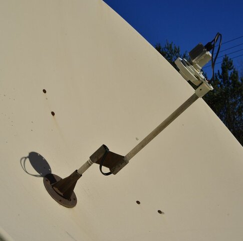
I have a button hook feed on a 12 foot dish for c band. It has the original Chaparral scalar and a C2W LNBF.
From reading here there seems to be a measure/ calculate f/d / position the scalar.
Not much on really tweaking the position of it. Kind of a George Foreman Grill thing. You know.
Guys. What to look for in peaking for maximum signals? If the scalar is too far in or out from the dish center?

One school of thought says the scalar acts like the secondary mirror of a Cassegrain telescope. It catches the signal from the rim of the dish, reflects it back towards the center, then blows it back to the feed throat.
Or it simply keeps the feed from "seeing" over the rim of the dish where interference may be picked up.

I'm trying to mentally understand the relation between scalar too far in and lnb positioned for maximum s/q and to far out with feed tweaked for max s/q. And where to find that happy place where it all peaks great.

My dish acts like it's sensitive to footprint. Like on 131W I have channels on certain tp's that are strong and others need a "bump" of the positioner a few clicks to peak signal. Hence the positioner memory slot 131W and 131W Bump.

Make sense?
 
This link should help on how chokes/scalars work How Do Scalar Rings Work

Its probably best you state what dish you have the settings needed will be in the specification of your dish it will save messing about measuring and calculating.
 
  • Like
Reactions: k.r.
The scalar gets put on the lnbf for the F/D of whatever your dish is. The, the WHOLE thing gets moved further or closer to your dish surface for the proper focal point. That might entail using washers on either side, to make it further away, or closer to the dish surface.

Do NOT just move just the lnbf in or out of the scalar to get focal point.
 
  • Like
Reactions: martin-f
Here's what we have. I had the F/D calculated. Set the lnb in the scalar as per specs. Managed to snag Reelz on 127W. Scoured up the right plumbing to assure the lnb throat was pointing right at the center of the dish. Crossed strings were within 1/4" of touching.
martin-f....i didn't keep my calculations. but at the time, my math was correct. it's a 12 foot fiberglass from the early/mid 80's with a very strudy polar mount. the mechanicals have been gone over with pillow block bearings to replace bushings and the arc peaked to perfection. seriously a well made no-name sat dish....no specs at all to refer to. but tons were installed here back then.
Tweaking the skew to get max signal w/o going in and out of the scalar was a bust. So I moved the lnb in and out and found I got a stronger signal.
The gray area tweaks from reading said that the throat "should be" ~3/4" out from the scalar. "About".
At that point the throat was over an inch out (towards dish center). So I moved the scalar in towards center, and backed out the lnb and started over again.
Eventually got a strong signal. It's the weaker tp's that makes tweaking difficult. My body obliterates signal.
So following the hard rule like you say prime. It kind of goes south.

The button hook has tons of adjustment. In, out, left, right.
Take 3860V on 101W. Very weak. Scalar is set and have been moving the lnb to see if I can get a stronger sig.
Was thinking of moving the scalar in and out 1/4" to see if I could get anything peaked.

So it makes me think. Are people with tripod scalar mounts who follow hard F/D rules missing out on the weak ones?

And as in the subject. What to look for when I move mine in or out. It's very difficult to do that with weak transponders when you body in front of the dish kills signal.
 
Hi your F/D should be set to the information you have and left at that distance, F/D ratio is calculated from your F/D this is the positioning of the scalar, when tweaking the scalar your F/D should be the same distance as when you started, what you need to do is ad washers to move the scaler leaving the LNB throat at your F/D.
 
Hi your F/D should be set to the information you have and left at that distance, F/D ratio is calculated from your F/D this is the positioning of the scalar, when tweaking the scalar your F/D should be the same distance as when you started, what you need to do is ad washers to move the scaler leaving the LNB throat at your F/D.
Cool. No washers needed.
Hi your F/D should be set to the information you have and left at that distance, F/D ratio is calculated from your F/D this is the positioning of the scalar, when tweaking the scalar your F/D should be the same distance as when you started, what you need to do is ad washers to move the scaler leaving the LNB throat at your F/D.

No washers needed. You can see the original placement for F/D. It was that way for years. And I double checked it. With the new LNB to get any signal at all I had to pull the throat back into the scalar. Original was a c/ku polorotor feed. So this is where I am to get an average 12-15dB signal on my os mio.
So that blows the set it and forget it thing out of the water. Suggestions to grab those weak ones?
 

Attachments

  • NIK_1061a.jpg
    NIK_1061a.jpg
    62.1 KB · Views: 320
Well, sometimes on certain dishes everything is a compromise. If yours doesn't like the "hard and fast" rule of F/D setting, adjust it however it works best for you. With a button hook mount, you are right. you don't need the washers routine with the feed, as you can move the entire buttonhook in or out.

However, many buttonhooks sag with age, and perhaps you do need to put at least 3 guy wires equidistant around the dish edge to the end of the buttonhook. You put turnbuckles on each one, and tension them carefully one at a time to make sure your feed is dead center and parallel to the dish surface when dish is pointing at your lowest receivable sat, yet still are the proper focal distance. I've done it on a 11.5ft fiberglass dish, and it can take a while to get it just right, but it's worth spending the time to do so.

As for blocking the signal with your body while doing all this, you have to move out of the way, check how it works, make a change, over and over until it's right. There's just nothing else for it.

Otherwise, you can go back to the polarotor method to tweak real weak signals. They are a bit better than LNBF's for that.
 
Adjusting the FD ratio setting by signal quality on a motorized dish may cause problems. The FD ratio setting is primarily responsible for attenuating off axis (non primary) lobes.

Example: Optimizing the SQ by varying the FD setting on a satellite without a similar frequency / polarity carrier from adjacent satellites, the main lobe may be maximized, but the side lobes also may no longer be attenuated. Likewise, if the FD setting is made on a satellite with similar frequency / polarity carriers on adjacent satellites, the side lobe attenuation procedure may decrease the main lobe performance on other satellites.

Always verify adjustments on multiple satellites, transponders and polarities. The best settings may be a compromise across the arc.
 
  • Like
Reactions: k.r. and phlatwound
Awesome input guys. In my quest of the tweak project what kind of signals are you getting on 103W 3860V? I had it then lost it. Weak (9.6 dB..up to 10.2) before the sun went down and it got chilly out.
Although the button hook is sturdy. Conduit is thick wall. A crow landing on it may deflect it a touch. Guy wires are a thought. Forget about feeding coax through with F connectors. That thick!
Just a question. Is it always a good rule, for example Brian's C2W-PLL, to have a definite "stick out" of the feed throat from the front of the scalar?
The Chaparral scalar is a bit thicker than the one that shipped with the lnb, and that's the one I'm using.
Thanks for the helpful input.
I am using a Tek2000 10ft mesh dish in the southeast US. Those you are trying to receive seems to be the Indemand Mux right? 3960H usually go ITC a lot but I am not sure about 3860V. At the moment of me typing this it's not ITC. I have noticed using the Titanium C1PLL I get 12.2db on 3860V and 3960H I get 14.5db.. Using just a run of the mill LNB I get 14.5db on the same transponder. If you are using a 12 footer you should be able to pull it in fine. It seems the PLL may reject some of the noise and the receiver picks up a lower signal rating. Just my 2 cents.
 
I am using a Tek2000 10ft mesh dish in the southeast US. Those you are trying to receive seems to be the Indemand Mux right? 3960H usually go ITC a lot but I am not sure about 3860V. At the moment of me typing this it's not ITC. I have noticed using the Titanium C1PLL I get 12.2db on 3860V and 3960H I get 14.5db.. Using just a run of the mill LNB I get 14.5db on the same transponder. If you are using a 12 footer you should be able to pull it in fine. It seems the PLL may reject some of the noise and the receiver picks up a lower signal rating. Just my 2 cents.

well 3960H is back scrambled this evening. didn't last long
 
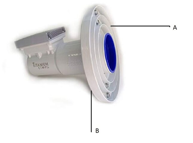
Simple question here. After determining f, where do I reference dish center to scalar placement. A or B?
Or as the Canadians would say..."Eh?"
And if my f/D is something like .31 would it be correct to assume the lnb throat would really stick out that far? Referring to the Titanium LNBF Install Guide.

Another side note. I use a backing wrench on the C2W-PLL to tighten the F connector. Is the jack on the lnb really supposed to be that loose? I can vision a wire inside stressing out.
 

Attachments

  • Scalar.jpg
    Scalar.jpg
    30.5 KB · Views: 265
The Focal Length is typically measured from the center of the reflector to 1/4" inside the feedhorn opening.

The feedhorn throat will be flush or extend past the scalar in an amount determined by the FD ratio setting.

NEVER use a wrench to tighten the F-fitting onto a port. Only finger tighten F-fittings. If the port is loose in the LNBF housing, the center conductor solder point will soon break from the PCB. You might get away with tightening the F-fitting port into the housing, but too much rotation and it will break the solder joint.

If I don't use a backer wrench to keep the lnb connector from turning, it will. With fingers only. It was loose from day one. Actually both of them are. The fittings on the coax are commercial ones my local cable tech gave me. Basically weather proof.
But the question remains. Scalar? Where to set it in relation to focal distance? And referenced from A or B? An inch futher back, a half, 2 inches from focus?
 
Have never previously observed loose F-fittings from the factory as they are assembled with rubber o-rings.

The FD setting is as shown on the Ti instruction sheet. When installing with the provided flat scalar, use the back of the scalar ring mount to align with the calculated FD ratio marking.

If using a different design of scalar, measure the difference between the two models and estimate the placement of the non-standard scalar. Alignment will be based on the calculated difference from the back of the scalar and the edge of the ring mount.
 
  • Like
Reactions: arlo
Have never previously observed loose F-fittings from the factory as they are assembled with rubber o-rings.

The FD setting is as shown on the Ti instruction sheet. When installing with the provided flat scalar, use the back of the scalar ring mount to align with the calculated FD ratio marking.

If using a different design of scalar, measure the difference between the two models and estimate the placement of the non-standard scalar. Alignment will be based on the calculated difference from the back of the scalar and the edge of the ring mount.

Great. Thanks. That clears the fog.
As for the fittings. They are that loose. When I first got the lnb from you it kind of freaked me out when I spun the F connectors on. I know you mentioned finger tight. But the wiggle had me down the ladder to grab a 7/16" wrench to keep them from spinning around. Can we do something about it?
 
You may send the LNBF in and I will rework the fittings or if you are comfortable with the process, the repair could be quickly done on your side.

Unscrew the 4 cover allen head type screws, remove the cover, desolder the F-fitting center pins from the PCB, tighten the fittings, resolder to PCB, clean old sealant from cover/case, apply new silicone sealant bead, replace cover.
Great. Thanks. That clears the fog.
As for the fittings. They are that loose. When I first got the lnb from you it kind of freaked me out when I spun the F connectors on. I know you mentioned finger tight. But the wiggle had me down the ladder to grab a 7/16" wrench to keep them from spinning around. Can we do something about it?
 
  • Like
Reactions: martin-f
You may send the LNBF in and I will rework the fittings or if you are comfortable with the process, the repair could be quickly done on your side.

Unscrew the 4 cover allen head type screws, remove the cover, desolder the F-fitting center pins from the PCB, tighten the fittings, resolder to PCB, clean old sealant from cover/case, apply new silicone sealant bead, replace cover.

Got it. Repair was easy. Got about 3/4 turn on both fittings before they snugged up. Wow. A touch of red Locktite on the threads and resoldered the connections. That's aced.
F fittings on coax by the way look like they have a teflon washer that seals the center pin when snugged up.
Anyway. The dish f/D works out to .31. So the lnb scale means nothing. Put side by side of the one that shipped with the C2W they (scalar ring) are almost identical. Just mine is a bit more robust.

Front of the scalar (A in the photo nobody seems to come up with a definite yes or no on) ended up being at focus. That being 37.1".
Throat of the lnb sticks out about 3/4" after tweaking for max signal. Gained around 2dB or a little more across the board.
Maybe not the best dish in the world considering when it was made.

It still is not clearly explained where exactly the FRONT (where you see the ribs) or the REAR of the scalar SHOULD be referenced to in terms of f. f/D or whatever.
So if a guy like me had a dish and scalar with no support arms or a button hook feed with adjustable length like me.
Some info on how to build those arms or set the scalar at the right distance from dish center would be cool.

Oh. And thanks for putting up with me!
 
How should our description of the Focal Length and Focal Diameter Ratio setting be changed?


The install sheet description and photos seem to be clear on how to set the scalar ring to the FD ratio stamped markings on the feedhorn throat and the FL measurement for the distance between the feedhorn opening and the reflector center.

Glad you were able to tighten the F-fittings into the housing. Now, only finger tighten...

Screenshot_20191119-071939_Drive.jpeg
 
  • Like
Reactions: 907TECH and FTA4PA

Users Who Are Viewing This Thread (Total: 0, Members: 0, Guests: 0)

Who Read This Thread (Total Members: 3)

Top