Switches Simplified

Status
Please reply by conversation.
answers 'n drawing specs

Iceberg said:
I thought you couldn't do a 22k with a Universal?
Does the ecoda work differently for that?
Linuxman said:
This is the precise setup I use with my Twinhan 1020a with 4 universals acting as standards with LO of 10600.
Yea, that's the cute trick.
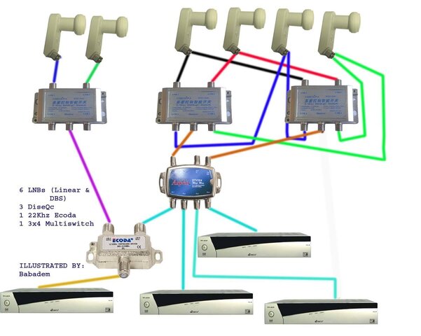
In dwg 4, above, the four LNBs on the right are on the 22khz On side of the Ecoda.
So, the right diseqc is sent a constant 22khz whenever it's selected.
That means all the right LNBs get 22khz.

So, if they are Standard, they ignore the tone...and their LO is 10750.
However, if they are Universal, they use the tone to switch into high band mode... and their LO is 10600.
Of course, the catch is that the Universals cannot switch to low band... but for 99% of the birds, that's just fine. ;)
I've picked up a lot of cheap Universals over the years, and this is a good way to get some use out of them.

The other side of the coin is that the four LNBs on the left side of the drawing cannot be sent 22khz tone.
So, if you really wanted to receive something with a Universal in the low band, you could put the LNB here.
But then there would be no way to switch it to high band.

I didn't say this drawing was perfect, just that it was my favorite. ;)
It's sort of a cheat, like hooking just one polarity of an LNB to only one side of a multiswitch, to get more LNBs.


I have a 90cm dish with a dual output Universal LNBF pointed at Galaxy 25.
I would like to connect up to 4 receivers to this dish. Is this possible?
All of the receivers will be emitting the 22khz tone to ask for the high LO.
Will they interfere with each other if I use a standard 3x4 multiswitch?
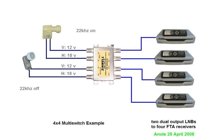
You seem to have a good grasp of the problem... and solution.
I believe what you have described should work fine.

I'll be getting to multiswitches over the next few days, as time permits.
Should get to complicated multiswitch/diseqc combinations by the weekend.

Anole,
I love your drawings, do you do those in Paint? I need to take lessons.
The secret is making up a library of pictures of around 100x100, up to 200x200 pixels.
At least that's how I started out.... at about 100x100 per icon, and my older drawings use that standard.
For the first two drawings of this series, I didn't have many elements, and to fill the page, I used 200x200.
But as the drawings get more complicated (there are several more to come), I'll revert back to the smaller size icons.

I also have other tools to flip and rotate the images before use.
It actually takes Lview to resize and flip, ACDsee to rotate and preview, plus Paint to make the icons into drawings.
Takes longer to say than to do.... once you have the pieces... but making the pieces is half the job. ;)

I'm actually about to audition another program, which may replace all of the above.
Not sure whether to change gears in the middle of this project or not.
... and this just in.... I may steal some nice finished drawings for part of the multiswitch discussions.
That'll save a lot of work by not duplicating work that's already done. ;)

. . . more to come . . . - :)
 
Last edited:
Ecoda 22Khz on side then to a separate 4x1 diseqc with the 4 Universals each on a separate port.

In the receiver, I select each port for it's satellite with 22Khz turned on. The Ecoda then sends to the 22Khz on side which passes through the diseqc to each individual LNB using only the 22Khz on high side of the LNB.

I don't know if other 22Khz switches work like that with Universals, but only the Ecoda switch will pass the diseqc commands.

that is good to know. I'm gonna have to try that. I have a Starchoice dish at 123 and am using the 0k side because I thought it wouldn't work. The signals arent as good as the LNB that has the 22k side (that LNB is straight down the LNB arm)...might have to try that out :)

So as long as the 22k side of the ecoda has that LNB it should work then? The LNB LO on the SC dish is 10750 22k on for that LNB
 
So as long as the 22k side of the ecoda has that LNB it should work then? The LNB LO on the SC dish is 10750 22k on for that LNB
Yes, it should work fine.

When choosing the LNB type on some receivers, the receiver may not allow you to choose whether the 22Khz is turned on or not, especially if you tell it is a Universal.

Then just choose standard and set the LO where you want it and all is well. :)
 
Can this setup work?

Can this diagram work in practice? I was thinking of using the following diagram to setup at least 3 boxes. Please, give me your feed back. See attachment.:)
 

Attachments

  • LNB Switch Diagram2 .jpg
    LNB Switch Diagram2 .jpg
    93.4 KB · Views: 254
That won't work because each diseqc switch will be getting commands from up to four receivers and they will conflict. Unless all four want the same LNBF at the same time, you're out of luck.
 
easiest thing is to take the dual LNB's and run them into 3 4x4 multiswitches. On each output of the multiswitch that goes to a diseqc switch for each receiver

so output 1 from each multiswitch goes to diseqc 1
output 2 from each multiswitch goes to port 2 of diseqc switches
etc
then each receiver can be set up the same
So technically my diagram on post #25 isn't practical?:confused:
 
nope. Not technology capable either :)

the only thing that would work is the far left item. The multiswitch being put between the diseqc and receivers won't work. Tried that a long time ago and nothing worked
 
multiswitches

Movin' On To Multiswitches

Recap:
Okay, we've covered two kinds of 22khz switches - the regular and the Ecoda.

We've dealt with one kind of diseqc switch (which come in 2-input and 4-input varieties)
Later in the advanced section, we'll get to the other kind.

Now it's time for basic multiswitches.
Again, there are two kinds, and we'll cover both.

Remember, this thread is organized for the beginner, with the easiest and most likely solutions listed first.
As we get deeper into the subject, the more exotic switch configurations will be dealt with.

Two Kinds of Multiswitches

They have two inputs or they have four inputs
That's it. Those are the two kinds. ;)
(hold your questions on 3- and 5- input switches for later*).

The two-input models require both outputs from a dual output LNB.
So, it's really a one-LNB switch... :(
The receiver selects Vertical or Horizontal by feeding the switch 12 or 18 volts, respectively.

The four-input model requires both outputs from -two- dual output LNBs.
So, it's really a two-LNB switch... :rolleyes:
As above, you select Vertical or Horizontal with 12 or 18 volts, and ...
... and, you select which LNB by supplying a solid 22khz tone or not.

Commonly available switches have two or four inputs and four or eight outputs.
There are some with more than eight outputs, but the basics described are the same.
We will deal with the simpler designs such as:
2x4 = two inputs (one LNB), and four outputs
4x4 = four inputs (two LNBs), and four outputs
4x8 = four inputs (two LNBs), and eight outputs for those really big jobs! :cool:

Recap: So, those are the two basic kinds:
- 2 input with no 22khz switch
- 4 input with a 22khz switch

* 3- & 5-input switches
These have one extra input to take your outdoor TV antenna and feed it down the same coax on your four (?) switch outputs.
In your living room, you would use a diplexer to split the feed, routing the satellite signal to your FTA box, and the local antenna signal directly to your TV set.
Because many installations will require other antenna-incompatible switches to follow a multiswitch, we will not give odd-input switches serious discussion.
Of course, if they are cheap, we can ignore the extra input. ;)
Diplexers also introduce some loss to your signals, so I'm not a big fan of 'em.

Using Two-Input Multiswitches

In our first example, we have one dual-output LNB and want to hook it to 2-, 3-, or 4- FTA receivers.
The switch has two inputs labeled: 12v and 18v.
Each puts out the marked voltage to one half of the LNB.
So, each half of the LNB puts out Vertical or Horizontal, respectively.
Depending on which voltage the FTA receiver supplies on its input cable, the switch gives the receiver the corresponding polarity.
And regardless of what other receivers want, both polarities are always available to all receivers.

Special Case: old Primestar LNB
Some, old Primestar (or similar) LNBs had two outputs, but one was fixed with the Vertical polarity and one was fixed with the Horizontal polarity.
Didn't matter what you did with the voltage, as they had no internal switches.
Using a 2x4 multiswitch to connect to both LNB terminals would work to supply all receivers with either polarity, just as in the first case.
Make sure you hook the LNB V terminal to the switch 12v input, and the H terminal to the 18v input.

Using Four-Input Multiswitches

The four-input switch allows you to connect two LNBs to many receivers.
The voltage switching works exactly as described above for two-input switches.
The extra trick to select between the two LNBs, is to use 22khz on or off.

dwg 5: two LNBs with a 4x4 multiswitch and four FTA receivers
I didn't think it was really necessary to post a picture with one LNB and a 2x4 switch.

These examples may seem too simple for many, but understanding how switches work lets you use them as building blocks for more complex switch installations.

. . . as we will see in future installments . . .
 

Attachments

  • Multiswitch_4x4_example.JPG
    Multiswitch_4x4_example.JPG
    40.9 KB · Views: 214
Multiswitch Example: simple

Real-World Multiswitch Example - 3 LNBs, 3 Receivers

Here is a design that was requested by a user who had specific requirements.
It may or may not suit your needs, but it's a good example of what we learned above.

Three receivers needed to be supported, and fed by any of three dishes.
The dishes had -
- a Universal LNB
- a DBS LNB for NASA/AngleOne
- C-band, and we used an uncommon dual-output LNBf with voltage control

Or maybe all the LNBs were on the man's C-band dish, just with various offsets.
Perhaps he moved it with his analog receiver.
It really doesn't matter for the switch discussion.

The 4x4 switch on the left uses 22khz tone to pick the C-band or DBS LNB.
It has four outputs to be routed to receivers or additional switches.

The 2x4 switch at the right feeds the Universal LNB to four outputs, and passes the 22khz tone to the LNB to let it select high band or low band.

The 2-input diseqc switches at the bottom let the receiver choose which multiswitch to listen to.

Obviously, you could have four receivers by adding one more diseqc and the 4th FTA box.
To expand this idea to support up to eight receivers, the multiswitches would need to be 4x8 and 2x8, respectively.

Likewise, you could add more LNBs and multiswitches if you had diseqc switches with four inputs (pretty common ones). ;)

dwg 6: three LNBs, and three receivers

Switch Information:
Code:
[FONT=Fixedsys]..
 C-band  : diseqc 1, 22khz off, 12v=Vertical 18v=Horizontal
 - DBS - : diseqc 1, 22khz on , 12v=Vertical 18v=Horizontal
Universal: diseqc 2, high band, 22khz on , 12v=Vertical 18v=Horizontal
Universal: diseqc 2, low band , 22khz off, 12v=Vertical 18v=Horizontal
[/FONT]
Up tomorrow? 8 lnb & 4 rcvr. Switch table & dwg are done. Busy day, so probably in the evening.
 

Attachments

  • 3dish3fta.JPG
    3dish3fta.JPG
    43.6 KB · Views: 220
Last edited:
Hi Iceberg,

On my setup to use the Universals, I have it like this:

Ecoda 22Khz on side then to a separate 4x1 diseqc with the 4 Universals each on a separate port.

In the receiver, I select each port for it's satellite with 22Khz turned on. The Ecoda then sends to the 22Khz on side which passes through the diseqc to each individual LNB using only the 22Khz on high side of the LNB.

I don't know if other 22Khz switches work like that with Universals, but only the Ecoda switch will pass the diseqc commands.

that is good to know. I'm gonna have to try that. I have a Starchoice dish at 123 and am using the 0k side because I thought it wouldn't work. The signals arent as good as the LNB that has the 22k side (that LNB is straight down the LNB arm)...might have to try that out :)

So as long as the 22k side of the ecoda has that LNB it should work then? The LNB LO on the SC dish is 10750 22k on for that LNB
Hey Ice, Considering the latest information (exception), I think you should update "The tip of the Iceberg #9":)
 
Multiswitch Example: serious

Real-World Multiswitch Example - 8 LNBs, 4 Receivers

For those readers who have been following along, this layout should pose no problem.

The LNBs need to have dual outputs, and be Standard.
The multiswitches are 4x4's. The diseqc switches are 4x1's.
Eight LNBs will satisfy all but the most die-hard T-90 users.
And if you need more than the four FTA receivers shown, this design is easily expanded to eight receivers with no problem at all.

Each receiver has its own diseqc switch to talk to.
The switch picks an output from one of four multiswitches.
Then, 22khz on or off picks the right or left LNB of each pair.

Switch Information:
Code:
[FONT=Fixedsys]LNB   diseqc   22khz
--------------------
 A       1      off
 B       1       on
 C       2      off
 D       2       on
 E       3      off
 F       3       on
 G       4      off
 H       4       on
[/FONT]
dwg 7: - 8 LNBs and 4 receivers
 

Attachments

  • 8-lnbs_4-rcvrsMarkIII-02.JPG
    8-lnbs_4-rcvrsMarkIII-02.JPG
    102.5 KB · Views: 253
Last edited:
Great thread Anole. This may be off Topic but since I now have 2 - C and 2 - KU working LNB's is it possible to show the hookup / drawing that Linuxman recently spoke about, that is the Chaparral Bullesye II Dual C/KU Feedhorn orthomode transducer? Do you need to purchase additional switches to power the 4 LNB's for V and H polarity? If so do these Switches need to be installed at the Dish, or can they be cabled back to the Dish from inside the House? And will they work with just a FTA type of receiver?
 
quad lnb / orthomode

Thanks.
I believe you can just use the left half of drawing #6, above.
Hook your two C-band LNBs to the two C-band wires shown on the switch.
Then, connect the two Ku-LNB outputs to the switch where the DBS LNB is shown.

If that's all you need, then connect the four outputs of the 4x4 switch to your four receivers.
If you want to bring in more LNBs, then take a look at drawing #7 for inspiration. ;)
In that case, connect the two C-band LNBs where the two outputs of LNB A go...
... and the two Ku LNB outputs to where LNB B goes to the switches.
 
simple stuff is done

Okay this thread was about simplifying the basic switches.
I hope we've covered all the basics, so the reader can come up with his own designs.
That means the job is done. - :rolleyes:

Getting Complicated

Going beyond eight LNBs or four receives, is getting into the more complicated realm.
I know some users would like to support twelve, sixteen, twenty, or maybe thirty-two LNBs , perhaps for their T-90 dishes.
Ya just can't get there with only the basic building blocks shown above.

There are DISEqC switches with eight inputs and one output.
They operate in diseqc 1.1 mode and that's not supported by all receivers.
Unfortunately, there is not enough info published by users here, for me to fully explain their operation.

A couple of members have posted reviews and usage descriptions of these 8x1 switches.
If anyone wants to take over and make a description of the full capability of any of these switches, I'll supply the wiring picture.
And I'm not sure the two 8x1's I've heard about, are equally interchangeable. :(
Need a list of capable and incapable receivers to go with any such further discussion, too.

As a hint of possible things to come, here are some 1-receiver ideas:
- FTA --- eCoda --- 2 each 8x1 diseqc = 16 LNBs (some restrictions on Universals)
- FTA --- 8x1 diseqc --- 4 each 4x1 diseqc = 20 LNBs (no restrictions on Universals)
- FTA --- 8x1 diseqc --- 8 each 4x1 diseqc = 32 LNBs (no restrictions on Universals)

Multi-receiver ideas I could envision right off the top, include:
- 8 each FTA receivers - 8 each 8x1 diseqc --- 8 each 4x8 multiswitch = 16 LNBs (Standard LNBs only)

But, since I don't know enough about the 8x1's, and don't have any to play with, the above ideas are just speculation.

Are we there, yet? - :D
 
My EMP Centauri 8X1 works well following a standard 4X1 Diseqc switch - so:
FTA ---- 4X1 ---- (4 EMP Centauri) 8X1 = 32 LNB's (universals OK)
FTA ---- Ecoda 22 khz --- (2) 4X1 --- (8 EMP Centauri) 8X1 = 64 LNB's (NO universals)
Bob
 
gettin' into the deep water

Oh, I was under the impression the 4x1 disecq's had to be between the 8x1 and the LNBs.
Didn't realize the 4x1's could be located between the FTA box and the 8x1's.
Well, that opens up a whole new list of available configurations.
Thanks . - :up

I contacted Iceberg today, and he's working up some more good descriptions and drawings.
That's what it'll take to get coverage on the 8x1's as I'm well out of my element with them.

If anyone needs 8x1 support drawings, I can help out.

And if anyone needs custom drawings for the less complicated stuff discussed in the first two pages of this thread, I'll try to help, too.
Or switch tables, too.
 
Thanks, Anole and the rest. I am now more confused, but I have read this thread about times and I am begining to understand. You have incorporated the answers to question in the thread and that is appreciated. I hope this can be built into a sticky.
Thanks again. OH YEAH -- the reason I was replying::: I tried to print the thread, but my connection crashed before it started. I do not know if I caused the crash or if the sever added too much. Is there an easy way to print out the thread?
TNX, POP
 
if you print out the thread it won't show the attachments (the pictures)

you can save the pictures to your desktop for easier review
 
Status
Please reply by conversation.