Titanium ASC1 Latest Update

  • WELCOME TO THE NEW SERVER!

    If you are seeing this you are on our new server WELCOME HOME!

    While the new server is online Scott is still working on the backend including the cachine. But the site is usable while the work is being completes!

    Thank you for your patience and again WELCOME HOME!

    CLICK THE X IN THE TOP RIGHT CORNER OF THE BOX TO DISMISS THIS MESSAGE
Status
Please reply by conversation.

Cham

VE4GLS
Original poster
Pub Member / Supporter
Dec 19, 2008
2,550
1,122
Boonies
Did the latest update on my main ASC1. Worked well. Actually added another step to make sure all was ok... hadn't done an upload to the ASC1 for quite a while (last update?), so I transferred the user data to the laptop using V 1.8 loader, reset the ASC1 memory, then uploaded the saved file back to the ASC1 to make sure the data would be read properly.

After doing the firmware update, the user data was transferred using the 2.0 updater. Unit seems to work fine.

Thanks Brian for the very detailed instructions and the update!

Now time to update my backup unit! :)
 
  • Like
Reactions: Titanium
Did the latest update on my main ASC1. Worked well. Actually added another step to make sure all was ok... hadn't done an upload to the ASC1 for quite a while (last update?), so I transferred the user data to the laptop using V 1.8 loader, reset the ASC1 memory, then uploaded the saved file back to the ASC1 to make sure the data would be read properly.

After doing the firmware update, the user data was transferred using the 2.0 updater. Unit seems to work fine.

Thanks Brian for the very detailed instructions and the update!

Now time to update my backup unit! :)
 
Hello,

I have carried out this update. Zero improve positioning repeatability when Jeager SMR 1224. The reason is that only one edge is counted. The positioning must count the Edge Low> High and High. > Low. Just as it makes the G-Box and V-Box II. In order to reach twice the resolution. These boxes drive error free. The Titanium ASC 1 brings in principle by the simple method of counting these errors.
If this change is not performed, the counting error will always occur. Since no update exploited without this amendment. I had already pointed out, but Gohl disagrees.

What did you think about that?

Ponny
 
Hello,

the software Insert the ramp when the engine is switched off. Circa 3-4 pulses before shut activate the ramp. Thus, the motor is switched off precisely without hunting.

It would be better still counting the two flanks Low> High and High> Low.

Ponny
 
I'm not really seeing what you re having an issue with. The latest update corrected all my counting problems with my high resolution sensors. No more reed relays or Schmidt triggers and capacitors needed. I did however leave the noise cancelling caps at the motors on my AJAKs. I also tested the new update with an optical sensor and ASC1 fitted with an OHR adapter (thank you for the idea) And no miscounting occurred. It makes me think there may be another problem you are having.
 
  • Like
Reactions: Titanium
Yeah I was wondering the same thing. What kind of cable are you using? Is it grounded at one end or the other. If proper shielded cable, only ground at one end and not both.
 
My posotioner has been working very nicely since updating, only had to re-calibrate once likely due to the mount shifting after strong winds.
 
  • Like
Reactions: Titanium
A sensor switch has only has two positions. There is no leading edge on a open and closed switch. A switch is either open or closed. Double counting the single cycle was used by a version of the G-box, but not on all other G and V-box controller models as you suggest. While this counting method displayed double the counts, it does not increase and provide more precise landing resolution. The only way to increase counts and landing resolution is to physically increase the number of pulse cycles generated per degree of rotation.

Motor voltage ramping function was removed from the firmware over a year ago. The current firmware does not have voltage ramping either.

The ASC1 logic first activates the sensor then applies motor voltage without ramp and it is not possible that 3 or 4 pulses are missed. This is the same logic used on legacy analog/4DTV IRDs and all commercial controllers.

Agree with the other posts that this current firmware greatly enhances compatibility with actuators, HH mounts and odd DiSEqC strings. Not sure what the issue is that continues to haunt your Jaeger. Too bad the SMR1224 has been out of production for so many years. It would have been great to have been able to bring their engineer in on this conversation.
 
Last edited:
Hallo,

Of this Problem Tritt nicht nur in der SMR im Jahre 1224, Sondern Auch, WENN Ajay and a hausgemachte Stellungsregler. Die Zählimpulse Werden von Reedkontakt Erzeugt. 12 Impulse Sind ein Grad hier. Da ich sterben following Stufen ausgeführt, sterben Eine sehr geringe Öffnungswinkel HABEN, spielt BEREITS Eine Impulsfehler Eine sehr große Rolle.
1. Laminas AS 1800
2. Laminas AS 2700
3. Netz 3.70m Wen Einzelstücke oft angefahren Werden, Werden Abweichungen vom Soll immer Grösser sterben. Das hat nichts MIT so weiter und Kabel zu tun. In Einem früheren Beitrag habe ich gezeigt, von der Impulse Oszillographenbilder. Dies ist ersichtlich, Dass der Reed-Schalter Wird manchmal überlaufen. Dann, Wenn Ein neuer Anfang schon ein Impuls gezählt Wird, Auch Wenn Der Motor Angetrieben Wird, nicht den schritt zu machen. Deshalb WIRD, WENN Rampe des Motors wieder ab in die Software setzen sterben. Die Idee Mit Dem Konverter von mir kommt. Es ist auf NÄHER Prüfung von Zählereingang optischer Encoder kein Adapter Notwendig. Der optical Codierer Hut Immer eine Openkolektor ausgegeben. Daher, Kann es direkt angeschlossen Werden. Es ist immer ein Widerstand 5 V gegen Erde Graf Geschaltet. Leider ist das nicht vom Hersteller Informationen angegeben.

Ponny
Ran this through Google Translate

Hello,

Of this problem occurs not only in the SMR in 1224, but also when Ajay and a homemade positioner. The counts of Will Reed Contact Creates. 12 pulses are a degree here. Since I die Following steps executed, which has a very small aperture angle HAVE ALREADY plays a pulse error A very large role.
1. Laminas AS 1800
2. Laminas AS 2700
3. Power 3.70m Wen Einzelstücke Are often approached Are deviations from the target always die Bigger. This has nothing MIT and so on to do cable. In a previous post I showed the pulses Oszillographenbilder. This can be seen, that the reed switch is sometimes overcrowded. Then, if A new beginning is already counted a pulse, even if the motor Driven If not the step to make. Therefore, IS WHEN ramp the engine die again put into the software. The idea With converter comes from me. It is on CLOSER examination of counter input optical encoder no adapter necessary. The optical encoder has always sent an Open Collector. Therefore, it can be connected directly. It is always a resistor 5 V to earth Graf Switched. Unfortunately that is not specified by the manufacturer information.

Ponny
 
Is that what you use now? A resistor to 5V on the sensor circuit and an optical sensor? ASC1 sensor circuit maximum 74hertz, is your pulses too fast?
 
OK, I really don´t get anything now....these translations make barely sense in German or English....Is there an original German version of this text? I will gladly translate but the version above loses lots of info in translation.
 
OK, I really don´t get anything now....these translations make barely sense in German or English....Is there an original German version of this text? I will gladly translate but the version above loses lots of info in translation.
The original is post #9 above.
 
That cannot be the original. It is of the same quality as the English version and definitely not native German (Grammar all over the place, wrong words...).Must also be automatically translated. Something is amiss here.
 
That cannot be the original. It is of the same quality as the English version and definitely not native German (Grammar all over the place, wrong words...).Must also be automatically translated. Something is amiss here.
Maybe Ponny will come on soon and clarify.
 
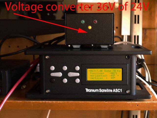
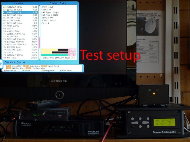
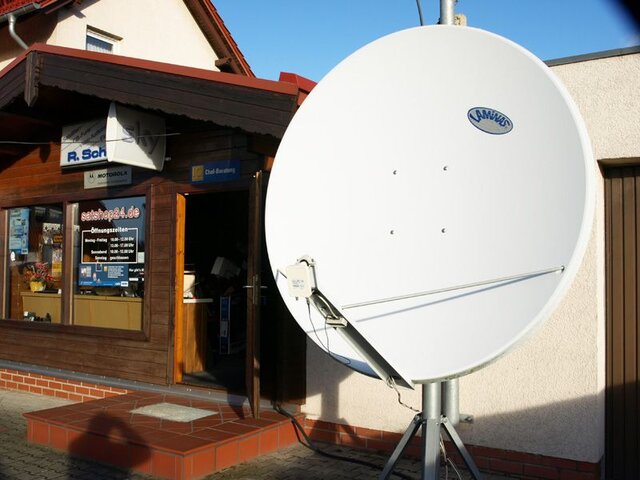
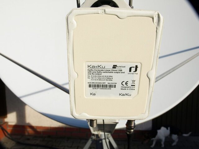
Hallo, der Regler geht in den Jaeger SMR 1224 und Laminas AS 1800 mit einem Spannungswandler von 36V bis 24V genau. Der Motor dreht sich somit langsamer und stoppt dann genau auf den Zählerstand. Es ist daher zwingend notwendig, wieder eingeführt werden, wenn die Rampe ausschalten. Dann verlangsamt sich der Motor ab, bevor die Satposition erreichen. Es gibt keine abschließenden. Es ist die einzig richtige Option zu dieser Positionierung Fehler zu beheben. Im Anhang ein paar Bilder von dem Test-Design mit der Laminas AS1800 und der Kombinierten LNB Ku (KA-Band von Inverto. Wenn Ka-Band bereits ein Dorn eine sehr große Rolle spielt. Ponny Übersetzung mit Google!


Hallo,
der Positionierer fährt with the Jaeger SMR 1224 und der Laminas AS 1800 mit Einem Spannungswandler von 36V auf 24V exakt. Der Motor Dreht Characterized langsamer und bleibt Dann exakt auf den Zählimpuls Stehen.

Deshalb sollte unbedingt sterben Rampe beim Abschalten wieder in Hollywood Werden. Dann bremst vor Motor schon der ERREICHEN der Satposition ab. Es kommt zu Keinen Nachlauf. Einzige richtige Variante um Diesen Positionierungsfehler zu beheben Es ist zu sterben.

Im Anhang ein paar Bilder vom Testaufbau mit der Laminas AS1800 und der Kombi-LNB Ku (KA-Band von Inverto. Beim Ka-Band spielt schon ein Fehlimpuls Eine sehr große Rolle.

Ponny
 

Attachments

  • Spannungswandler.jpg
    Spannungswandler.jpg
    67.1 KB · Views: 406
  • test-setup.jpg
    test-setup.jpg
    64.9 KB · Views: 281
  • Laminas_AS1800.jpg
    Laminas_AS1800.jpg
    66.5 KB · Views: 291
  • KA_Band.jpg
    KA_Band.jpg
    40.5 KB · Views: 308
Hello,
After intensive testing the counting error still occurs. Not as extreme as with 36V, but it's still there.
A new problem has come with the Ka / Ku-band LNB to. The LNB voltage breaks down in the vertical plane. The current limitation talks with the vertical plane of it only helps the positioner To disconnect and then on again. Horizontal it works.

To the receiver without positioner there are no problems. How can I change the admissible power consumption when ASC 1 enlarge, or limitation?

Ponny

Hallo,
nach intensiven Test tritt der Zählfehler immer noch auf. Nicht so extrem wie mit 36V, aber er ist noch da.

Ein neues Problem ist mit der Ka/Ku-Band LNB dazu gekommen. Die LNB Spannung bricht in der vertikalen Ebene zusammen. Die Strombegrenzung spricht bei der vertikalen Ebene an Es hilft nur den Positionierer Auszuschalten und wieder Einschalten. Horizontal funktioniert es.

Mit dem Receiver ohne Positionierer gibt es keine Probleme. Wie kann ich die zulässige Stromaufnahme beim ASC 1 vergrößern, oder die Begrenzung ändern?

Ponny
 
What is happening to improve landing accuracy when the motor supply voltage is reduced from 36Vdc to 24Vdc when using the SMR1224? Since this voltage reduction is performed externally and the ASC1 still supplies the same voltage to the motor circuit and reads the same sensor pulses, why is the 1224 operating differently? I see on other forums that for several years, hobbyists have been reducing the voltage on G-box and V-box controllers to 24Vdc for their SMR1224 motors to improve accuracy. Why is this necessary if the SMR1224 is rated at 36Vdc? This appears to be a known issue with the SMR1224 that is addressed by reducing the supply voltage to 24Vdc?

As we are not seeing landing accuracy issues or sensor errors with AJAK, Von Wiese, Venture, Super Jack or other commonly available actuator/motor units, why is your SMR1224 operating so differently?

Are counts missed or is the SMR1224 motor not landing accurately?

Do you observe a higher noise threshold amplitude on the sensor circuit when the SMR1224 is supplied with 36Vdc?

Does the SMR1224 run past the desired landing point when supplied with 36Vdc, but the motor stops sooner if run at the lower 24Vdc?

What is the amperage draw of the KA LNB when supplied 18Vdc? At power-up? During operation?

What is the amperage draw of the KA LNB when supplied 13Vdc? At power-up? During operation?

The LNB current draw will be greater when the supply voltage is at 13v and current draw will be lower when the supply voltage is 18Vdc. The current draw will also be higher during the power-up of the LNB and reduce once the LNB electronics are powered and operational.

The ASC1 is rated for 450mA operating current draw and the reset protection is activated at approximately 650mA maximum draw. Your LNB current requirement is exceeding this maximum limit. The limit is set to protect the ASC1 hardware and setting the current protection to a higher level will stress the hardware by allowing the over current draw and ultimately damage the controller. Changing this current protection setting is only masking an over-current demand by the attached hardware. It would be best to provide the correct voltage and amperage to power the connected hardware, rather than defeat the protection and exceed the ASC1 ratings. Your receiver may allow a slightly higher current draw before the hardware interrupt happens, but I am not aware of any receiver hardware designed for current draws in excess of 550mA.
 
Hello,
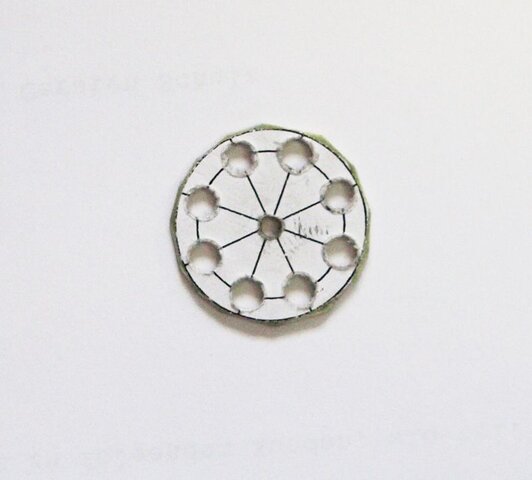
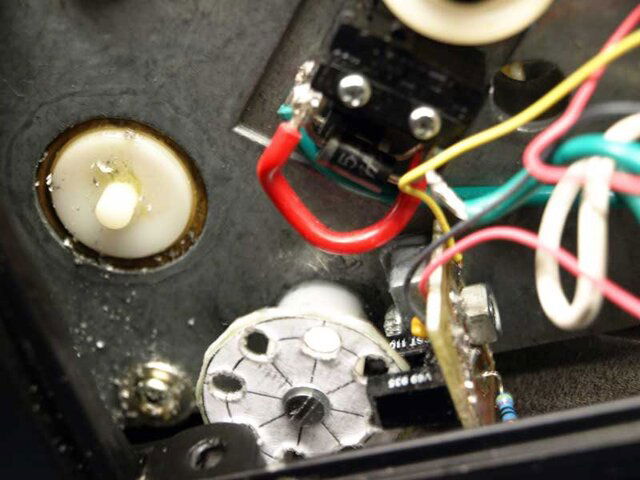
have installed after I an optical sensor in the hunter SMR 1224 was the number of pulses for 1 ° be doubled.
1. The counting error still occurred anyway. The positions were fine positioning with the remote control of the ASC. 1
2. Drive and positioning directly with DiSEqC 1.2 from the receiver Dr.HD D15. Here, the error did not occur. It all items have been approached with 100% recovery accuracy.
3. Conclusion, here is a software error in the fine adjustment with the original remote control of the ASC 1 before. I request the removal of the fault.

In the appendix a few pictures, as I have installed the optical sensor in the MR 1224th
Furthermore, as the optical encoder is connected directly to the ASC. 1 No adapter is required for optical pulse.

Ponny


Hallo,

nach dem Ich einen optischen Sensor in den Jäger SMR 1224 eingebaut habe konnte die Impulsanzahl für 1° verdoppelt werden.

1. Der Zählfehler trat trotzdem noch auf. Die Positionen wurden mit der Fernbedienung des ASC 1 Feinpositioniert.

2. Fahren und Positionieren direkt mit DiSEqC 1.2 aus dem Receiver Dr.HD D15. Hier traten die Fehler nicht auf. Es wurden alle Positionen mit 100% Wiederkehrgenauigkeit angefahren.

3. Schlussfolgerung, hier liegt ein Softwarefehler beim der Feinjustage mit der Originalfernbedienung des ASC 1 vor. Ich bitte um die Beseitigung des Fehlers.

Im Anhang ein paar Bilder, wie ich den optischen Sensor in den MR 1224 eingebaut habe.
Weiterhin wie der optische Geber direkt an den ASC 1 angeschlossen wird. Es ist kein Adapter erforderlich für optische Impulsgeber.


Ponny
 

Attachments

  • Impulsscheibe.jpg
    Impulsscheibe.jpg
    37.2 KB · Views: 254
  • Ansicht-1.jpg
    Ansicht-1.jpg
    41.7 KB · Views: 236
  • Ansicht2.jpg
    Ansicht2.jpg
    41.7 KB · Views: 270
  • Impulswandler.sch.pdf
    23.9 KB · Views: 236
Ponny,

Thank you for sharing your testing information. I need some clarification as information that you shared in earlier posts seem to provide incorrect and incomplete information.

1. Have you verified our information regarding the double edge counting of a single pulse cycle requirement does not apply as stated in post #3?

2. Have you verified that the ramp voltage is not present as stated in post #4?

3. Have you verified that the 36Vdc or 24Vdc motor supply voltage makes no difference to the correct DiSEqC 1.2 STB positioning as stated in post #17?

5. What are the KA LNB current draws at 13Vdc, measured during start-up and during operation as requested in post # 18?

6. In post # 19 you indicate proper positioning using the STB with DiSEqC 1.2 commands. Is this a "GoTo" a previously saved motor position number?

7. Does the motor position correctly when the STB's East or West button is used to manually drive via DiSEqC 1.2 commands to a counter display position? Continuous move mode? Single step mode?

8. Does the motor position correctly when a target motor position number is selected via the ASC1 front panel buttons? This position "GoTo" call out is identical to the STB DiSEqC 1.2 call-out.

9. Does the motor position correctly when a target motor position number is selected via the ASC1 remote? This position "GoTo" call out is identical to the STB DiSEqC 1.2 call-out.

10. Does the ASC1 remote control positioning error happen during manual driving to a specific counter number? Continuous move mode? Single step mode?

11. Does this error also occur when using the ASC1 front panel buttons? Continuous move mode? Single step mode?

Thank you for the additional information and clarification. Your replies will help us test and attempt to replicate with correct information.
 
Last edited by a moderator:
Status
Please reply by conversation.

Users Who Are Viewing This Thread (Total: 0, Members: 0, Guests: 0)

Who Read This Thread (Total Members: 3)

Latest posts