hey guys,
here is how i did the modification
i have rigorously tested it and it is working great and passing diseqc commands to my switch like its going for a touchdown.
")
i didn't use surface mount stuff, it just seems to take all the colour out of the circuit board.

plus i went into this project wanting to find the easiest way to do it right so other people could do it as well.
")
I AM NOT TELLING ANYONE TO TRY THIS, IF YOU DO, IT IS AT YOUR OWN RISK!!!!!!!!
anyway,
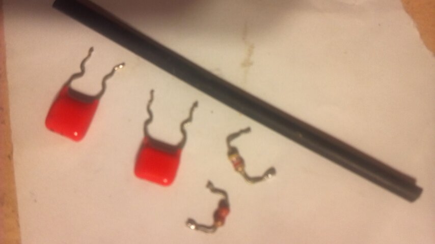
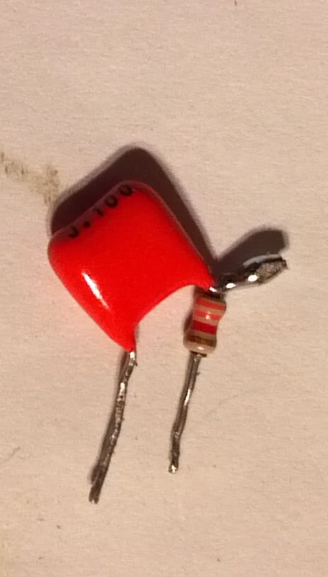
parts i used, (see pic 1)
3.3k ohm 1/8 watt resistor - orange, orange, red, gold
4.7k ohm 1/8 watt resistor - yellow, violet, red, gold
10nF (0.01uF) non-electrolytic capacitor - 103
100nF (0.1uF) non-electrolytic capacitor - 104
(all scavenged out of an old crt computer monitor)
small piece of heat shrink tubing
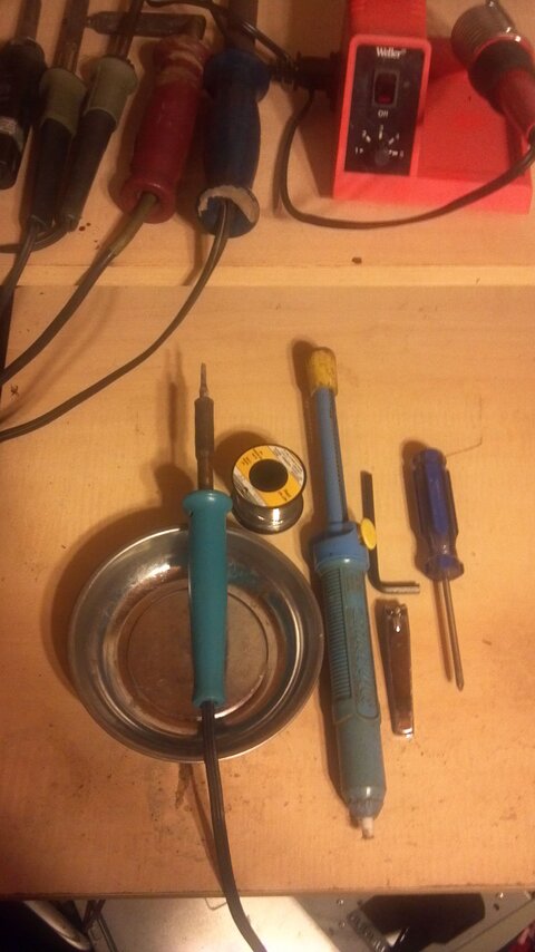
tools i used, (pic 2)
soldering iron
solder sucker
0.8mm 60/40 rosin core solder
(NOT rohs compliant, maybe a bit poisonous, but solder without lead sux...
)
toenail clippers
allen wrench
phillips screw driver
small tray for screws and parts
For DiSEqC pass-through
step 1. unplug and unhook everything from the asc1
step 2. remove the screws on the bottom
step 3. ease it apart enough to unplug the wires from the main board
step 4. remove 4 screws holding the main board and remove the board
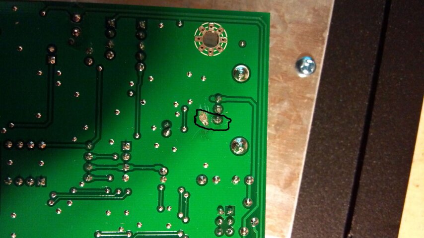
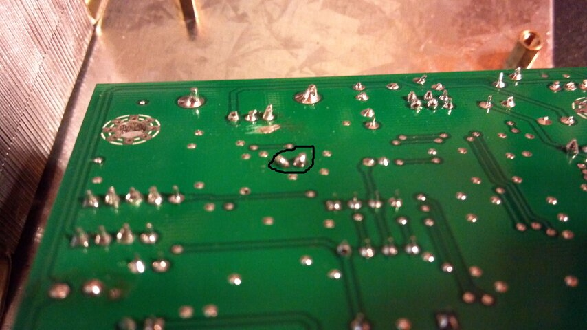
step 5. heat up your soldering iron and remove the small surface mount capacitor on the back of the main board
already removed but location shown in (pic 3)
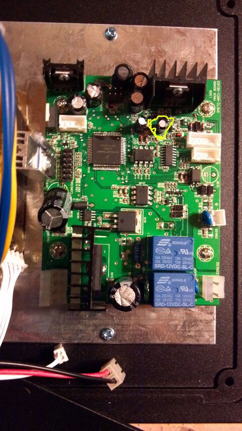
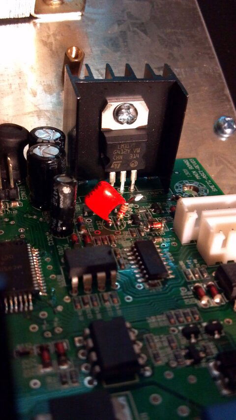
step 6. remove the electrolytic capacitor c132 (pic 4)
step 7. twist 1 leg of the 100nF cap and the 3.3k ohm resistor, solder them together, then use the toenail clippers to shorten the leads you just soldered (pic 5)
step 8. solder this in place of the electrolytic capacitor you removed in step 6 (pic 6) and clip the excess length off the leads with the toenail clippers (pic 7)
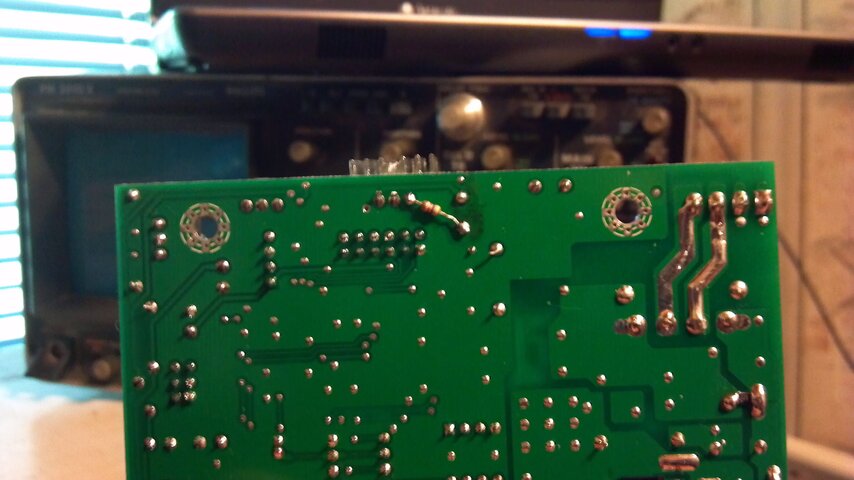
step 9. remove r106 being very careful not to disturb r105 (pic 8)
step 10. solder the 4.7k ohm resistor on the back of the board from the negative side of the large electrolytic capacitor c107 to the closest leg of u102 (pic 9)
To increase sensitivity to DiSEqC commands
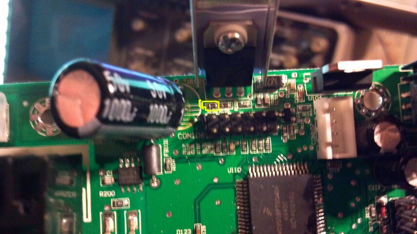
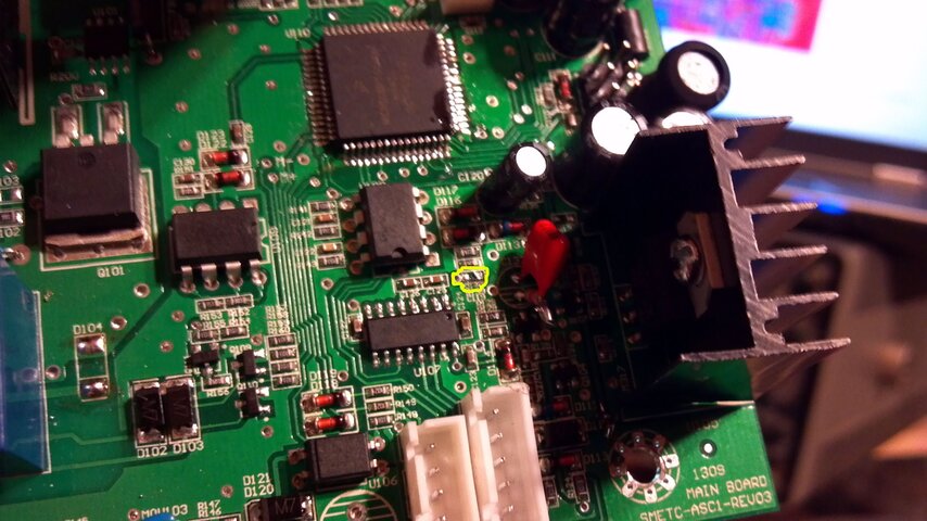
step 1. remove the small surface mount capacitor c119
already removed, but location shown in (pic 10)
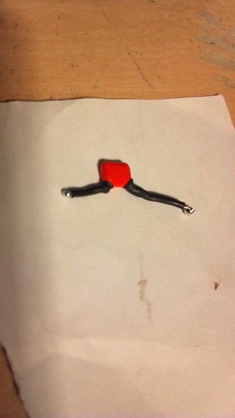
step 2. put heat shrink tubing on the legs of the 10nF capacitor, heat it to make it shrink, then put a small ball of solder on the end of each leg. (pic 11)
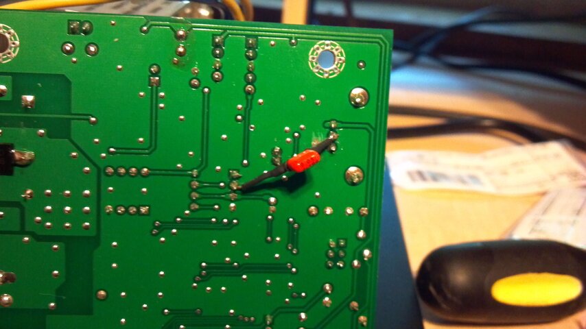
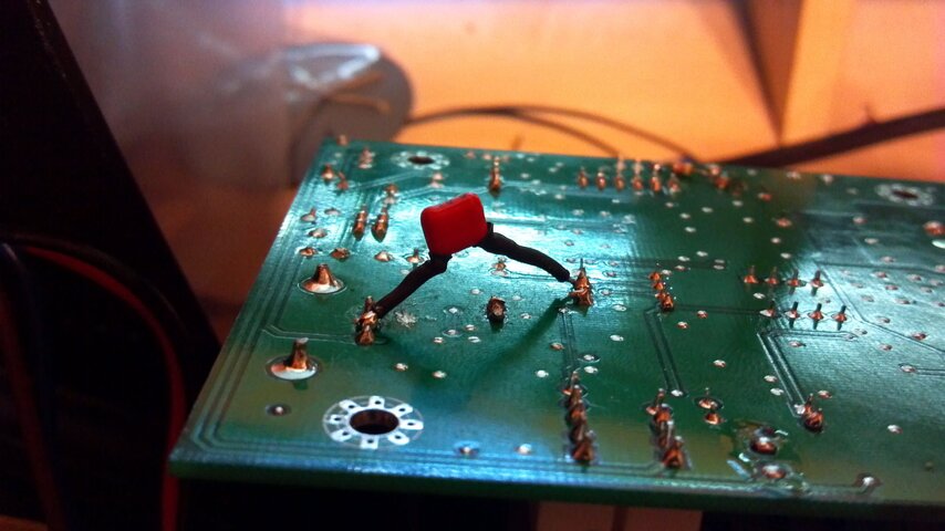
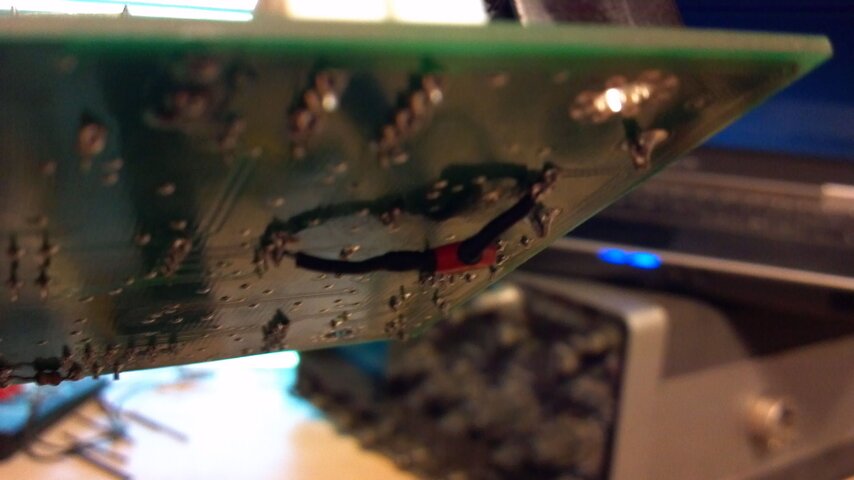
step 3. solder 1 leg of the 10nF capacitor to the centre pin of u105 on the back of the board and solder the other leg to pin 2 of u108 on the back of the board (pic 12). notice the angle the legs are at in (pic 13) just after soldering. this will help keep the legs from shorting against anything when the capacitor is bent down to its permanent location (pic 14).
note that there is still a gap between the legs and the board in pic 14 to help insure there is no accidental contact with anything else.
all in all, not to hard to do. it took longer to post this than it did to do the mods!!
hope this helps,
Denny