Birdview reed sensor kit

Status
Please reply by conversation.
Well I feel like Audi Murphy in a certain movie he starred in.

I've been there and back.

I got all the magnets lined up nice and even with the wheel, put the black cylinder sensor in place and got no counts. I went out and found another sensor that is flat on another actuator head, put it in place and it only saw a few out of the 24 depending on where I put it.

Called Anole, talked about it to him. He thought I should turn every other magnet around so that half pulled and half pushed. Wouldn't give me any more counts than 12, but would at least do that. I didn't want to do that, but ended up taking 12 magnets off. I figured if I was only going to get 12 counts, I might as well try the 2 switch trick.

After down to 12 magnets evenly spaced, the black cylindrical would have 6 counts, and the flat one would have 8. So I put the 12 magnets back on and let it set to dry for an hour.

Meantime I went up to the roof and changed out an LNBf on G10 just to kill time and it was nice out. 60F

I hooked it all back up and same situation. If I held the sensors extra close, I could get 6 counts out of the black cylinder and 8 out of the flat sensor.

As a last resort, I hand held the little glass fifty cent sensor up next to the magnets and started the motor. If I held it just right and right next to the magnets almost rubbing them, it counted perfectly 24 counts and did it consistently.

So what I need is to figure out a holder for that jewel, or buy a super sensitive sensor from Digi-key. BTW, I can get more of these fifty cent sensors Thursday because I will be going right by there.

So I am at a stand still for now.
 
I don't know if it would work but I would check out an alarm installation company for Ademco resessed contacts. They come either as 3/8 with a lip on the front or 1/4 inch smooth. They also have some with a magnet in them which makes them closed until an opposite magnet gets close. I had to change the magnet on my motor home door because the steps kept going out while we were driving. If I could find my box of alarm parts I would sent you a couple of each to try, for the goodof the forum, but I have NO idea.... When I do, I will offer them!
 
They come either as 3/8 with a lip on the front or 1/4 inch smooth. They also have some with a magnet in them which makes them closed until an opposite magnet gets close.
That's an interesting concept. I'll try to find an alarm installation company.

Thanks!
 
After spending an hour on the phone this afternoon trying to find a reed switch locally, I decided to start calling some of these manufacturers.

I talked to a very knowledgeable old timer at Phoenixamerica referenced above in one of Bryan's posts. He even knew what C-Band dishes and actuators were. Said they used to make some stuff for Houston Tracker. :)

He knew exactly what I was talking about and what I was trying to do.

He said that it shouldn't make any difference whether the magnets were pushers or pullers. The only difference it might make is if I had a biased switch and he told me how to test for that. He said the other problem might be that all magnets might not be equal strength.

They don't make a wheel like I need or I would have bought one. He also said reed switches can be damaged by harsh physical banging etc., which would change their characteristics. He also said the best bet for a new switch was Digi-Key.

I talked to a guy at cherrycorp.com who makes reed switches and sells them through Digi-key and he suggested that I forget all the 24 magnets and just use one stationary magnet, cut the steel end out of a coffee can, make evenly spaced gaps around the edge, 24 if I want and put the switch directly opposite the magnet. His "gear" wheel as it spins allows the magnetic pulse through in the gap, and stops the magnet "flux" when steel is in front of it. He said it would be very easy to test using the steel wheel with just one or two gaps in it.

That will be my next part of this project. Easy to test, and easy to make if it works. :)
 
I am impressed!

Linuxman, you really have made some headway on this project! I'm very impressed with what you have prototyped thus far. I like the idea of the coffee can top. Very similar to the optical method, but using magnetic flux instead of light. I have seen this used with hall-effect switches but I was not aware that it will work with reed switches too.

One thing that I thought of about the coffee can lid...it may be easier to drill holes close to the periphery than it would be to cut out notches. Not that it is really needed, but it will also give more strength to the disk. When you are done it would kinda look like the plastic dial from a rotary phone.

Another alternative that might work: a sprocket from an old bicycle.
 
One thing that I thought of about the coffee can lid...it may be easier to drill holes close to the periphery than it would be to cut out notches. Not that it is really needed, but it will also give more strength to the disk. When you are done it would kinda look like the plastic dial from a rotary phone.
Thanks Bryan!

The coffee can lid idea works with at least two notches cut into it.

It was fine for the test, but will need a more rigid material for the real thing. I like your idea about drilling the holes near the outside edge. I'll see if I can find a 24 tooth gear with the right diameter and right shaft size. That would be superb if the gaps etc were just right. The tolerances are very close so you would need a rigid wheel, a rigid holder for the switch and magnet, but it will be much easier than the 24 magnets. :D
 
I found an old circular saw blade out back. The hole in the center is fine and is pre-drilled.

It will be very rigid and is about 1/16" thick. Just have to cut out 3.25 inches out of the center and put holes or notches in the outer rim. My only concern is that it might be hard to cut, but I never did buy expensive blades and am trusting that this one is a cheaper one made out of a less tough grade of steel. If it is too hard, I can always find something up at the scrap yard tomorrow. :)
 
poor man's magnetics

I wouldnl't even consider a used saw blade unless it were already the right size!
Too hard, and too dangerous without a proper shop and tools.

You might check the Salvation Army (or similar) store for a suitable bicycle for parts, I suppose.
Maybe Police Impound lot...? A trash dump? I'm sure many get lost or trashed.
I don't give a lot of hope to that, either.

Got your message about the reed sensors not doing a very good job.
Don't know if it's a contributing factor, but if the disc wobbles or the magnets aren't the exact same height, you'll have that problem.

Here's something we didn't discuss.
With 24 magnets all facing the same way, spread around the periphery of the disc, you wind up with a toroidal magnetic field around the edge of that disc.
With the magnets so close, the field, in three dimensions, looks like a doughnut centered on the edge of the disc (roughly).
I suspect that field is keeping your switch closed as the disc rotates.

There are two things that could be tried, and I'll list them in order starting with easiest.

1). turn the reed switch so it's 90º to the row of magnets.
Right now, I think you have the reed long ways along the path the magnets travel
Or to say it another way, turn your reed up 'n down instead of parallel to the deck plate as it's shown in your pictures.
That would prevent the reed from being affected by the "next" magnet.

2). my other idea was to make a wheel with little saw kerfs in the edge.
Thin disc magnets would be set into the kerf , and oriented: N:N and S:S
In other words, the magnets would push away from each other.
I'm picturing the 8mm x 1mm discs I found at DealExtreme.
That is a theory based on the fact that if adjacent magnets were: N:S, they'd attract each other, and the magnetic field would be contained, not spill out the side to actuate your reed.

Unfortunately, my knowledge of magnets is based on what I learned in grade school, and from some super-strong ALNICO devices my Dad brought home from Cape Canaveral.
That pre-dates the ceramic and rare-earth magnets, so I'm a little behind the times. ;)
Even someone with a current degree in Physics, may not have specialized in magnetics enough to help us, but if we have any such person, please do jump in! - :up

edit: I went back and re-read some material I'd missed in this thread.
For hacking the coffe can lid, if you have a nibbler tool, that should make quick work of the rim of your lid.
I think Radio Shack sells 'em for $13.
Just don't cut yourself on the sharp edges.
 
Here's something we didn't discuss.
With 24 magnets all facing the same way, spread around the periphery of the disc, you wind up with a toroidal magnetic field around the edge of that disc.
With the magnets so close, the field, in three dimensions, looks like a doughnut centered on the edge of the disc (roughly).
I suspect that field is keeping your switch closed as the disc rotates.
I had decided not to try the saw blade too, just too hard. So while I was waiting for tomorrow to come, I thought I would try your trick of turning every other magnet so that it pushes instead of pulls.

I have been waiting for the glue to set for a while, but will try it shortly.

I did test the switches and they are not "biased" switches. The test is conducted by passing the switch across both sides of the magnet. If you get a pulse on both sides, it is not "biased".

1). turn the reed switch so it's 90º to the row of magnets.
Right now, I think you have the reed long ways along the path the magnets travel
Or to say it another way, turn your reed up 'n down instead of parallel to the deck plate as it's shown in your pictures.
That would prevent the reed from being affected by the "next" magnet.
I'm not clear on that one, but will re-read a few times and try and figure it out.

The two switches I am trying out other than the glass uncovered switch are placed as:

The cylinder shaped one has the head sticking out of the brass tube at a 90 degree angle of the turning wheel with the head aligned with the row of magnets.

The flat shaped switch is aligned the same way I took it off the old actuator in the back. The front of the flat piece lines up with the magnets as they travel around on the wheel.

2). my other idea was to make a wheel with little saw kerfs in the edge.
Thin disc magnets would be set into the kerf , and oriented: N:N and S:S
In other words, the magnets would push away from each other.
I'm picturing the 8mm x 1mm discs I found at DealExtreme.
That is a theory based on the fact that if adjacent magnets were: N:S, they'd attract each other, and the magnetic field would be contained, not spill out the side to actuate your reed.
Do you mean place the magnet sideways into the wheel instead of flat on the wheel?

For hacking the coffe can lid, if you have a nibbler tool, that should make quick work of the rim of your lid.
The coffee can lid was just for the test. It is un-suitable for the real thing. Too thin and wobbly especially after you cut a couple of gaps out of the edge. :)

Am about ready to try the every other magnet reversed theory. Will report back soon. :D
 
WooHoo!!!!! :cool:

It works!!!!!!!!!!

Picture me jumping up and dancing in the street outside shouting, laughing and all in my shorts and tee-shirt. :D

The next time I get a stubborn streak or get lazy Anole, please remind me like I do sometimes to go back and re-read post number whatever and this time do it!!

Seriously, thank you for everyone's help.

I may or may not pursue the gapped wheel. I have already spent several days on this project, and still have to tidy it up for it to be finished.

I might let Bryan run with that one.

I am getting a consistent 24 pulses per revolution going through 3 complete revolutions in both directions with both switches and have about 1/8 - 1/16 inch clearance between the magnets and the switch.

Linuxman is a very happy camper!!!
 
HeHe!

I'll post pictures of the finished product. It is the same thing as the last pictures except the magnets are all even now, but I will post pictures when it is finished up.

Thanks!!
 
a little something to chew on . . .

Congrats on your success ! - :up

I recall the idea of using two switches, to double the pulse count.
That can work, if the duty cycle you get from one switch , is significantly below 50:50
One way to reduce the duty cycle is to move the magnets apart.
And use of 12, certainly did that.

So, here's another thought . . .
Put maybe 18 magnets around the circle and have switches at two places.
The overall pulse count would be 36 per revolution. ;)

I'm not -real- serious about that idea, but as I said, it's something to chew on . . .
 
Thanks Anole for all your help and suggestions.

I agree that it might be possible to get 36 counts as you suggested by the use of two switches. I hope the ideas from this thread will help others with low counts on their actuators.

It is possible to make improvements with minor modifications to existing equipment.

I hope Bryan can get some time to pursue the wheel with gaps using one magnet. I would like to see how that pans out. :)
 
Ok Al and everyone else.

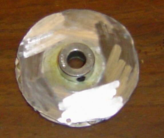
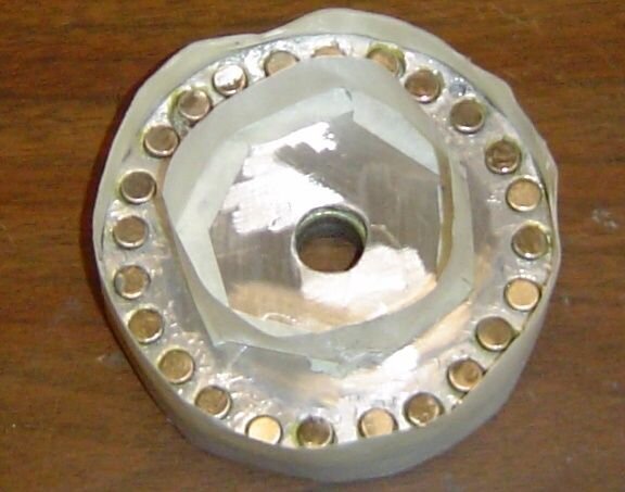
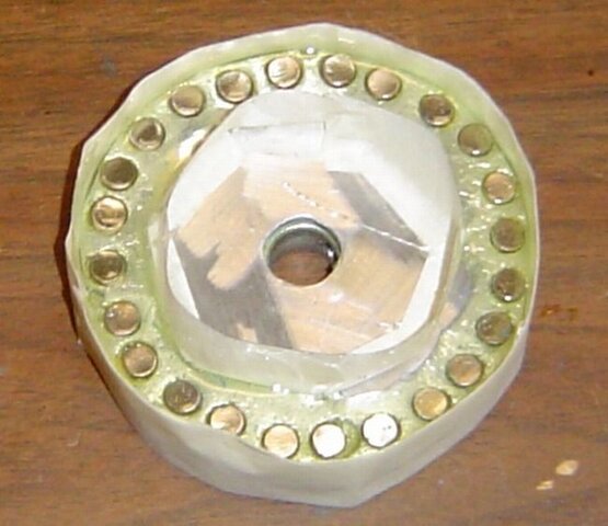
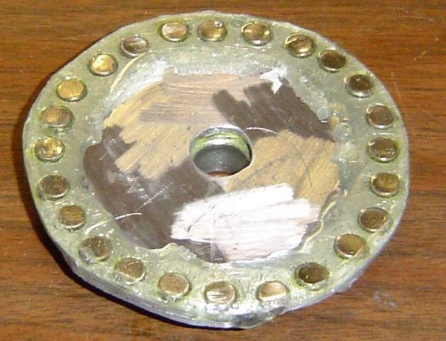
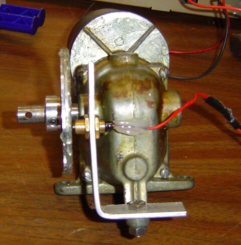
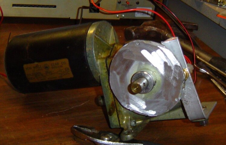
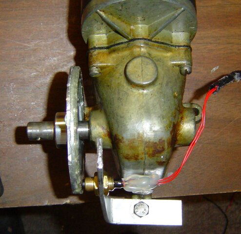
The finished product pictures as promised. There are a bunch of them and I tried to put them in order.
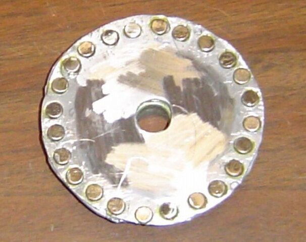
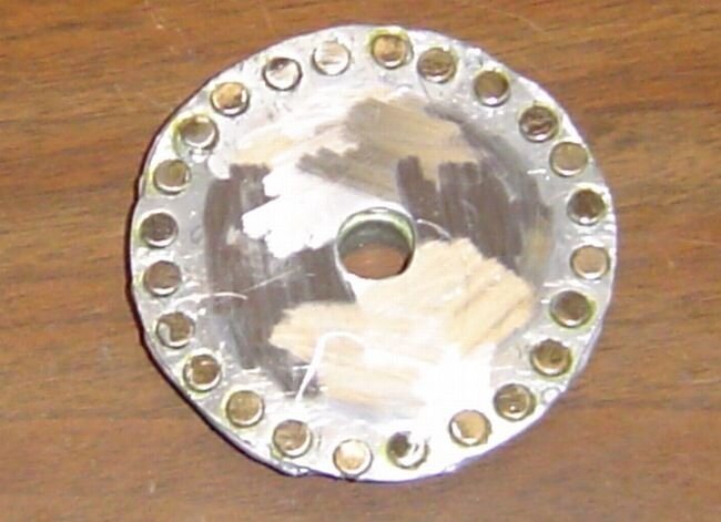
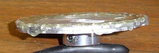
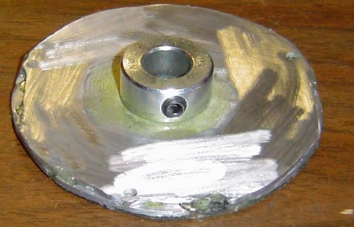
magnet-wheel-before-cleaning.jpg cleaned-magnet-wheel1.jpg cleaned-magnet-wheel-back.jpg magnet-wheel-with-channel.jpg

magnet-wheel-channel-epoxy.jpg magnet-wheel-epoxy.jpg magnet-wheel-epoxy-flat.jpg magnet-wheel-epoxy-back.jpg

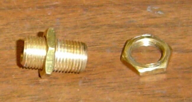
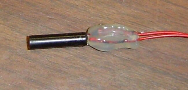
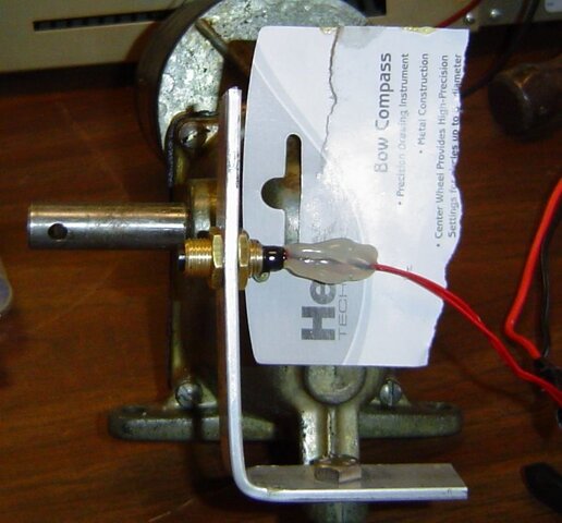
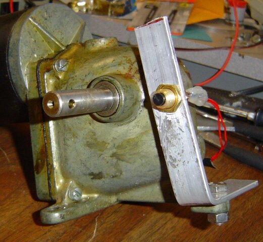
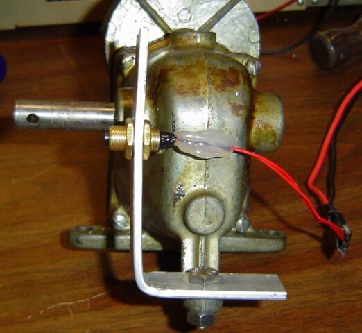
quarter-inch-brass-close-nuts.jpg cylinder-plunger-reed-switch.jpg attach-reed-switch.jpg attach-reed-switch-side.jpg

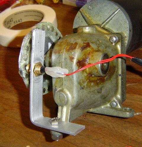
attach-reed-switch-final.jpg final-assembled.jpg final-assembled-front2.jpg final-assembled-side.jpg

final-assembled-top.jpg

To make one exactly like the above model, you will need:

2 - 1/16" X 3-1/4" dia round aluminum plates.
1 - 1/2" locking collar (good quality that is the same dimension all around)
24 - 1/4" dia X 1/8" thick strong magnets
1 - 3/8" X close brass pipe nipple (package labled it 1/8", but package was wrong) 1/4" ID so whatever it is?
2 - 3/8" brass nuts (takes a 9/16" wrench)
1 - cylinder/plunger type non-biased reed sensor switch
1 - 1/8" X 3/4" aluminum bar stock (bend to fit)
1 - Bottle Contact Cement
1 - Tube Epoxy

I drilled 24 - 1/4" holes spaced evenly around the outer perimeter of the front piece. Yes I had to reem out the holes a little to get the magnets to fit in. Drill a 1/2" hole in the dead center of both pieces (again reem out just a little). Sand the plates a little to create good sticking surfaces, then chemically clean with alcohol and cement the two plates together. Next, cement the locking collar to the back plate and allow all to dry for at least an hour.

Lay out the magnets on a flat table far enough apart so they don't all jump together in a cylinder. :)

Put contact cement in every other hole with a tooth pick sparingly. Place the magnets with the side up that will be placed in the holes. Apply contact cement onto the magnets. Allow both surfaces to dry at least 10 minutes.

Insert the first twelve magnets in the glue applied holes making sure they all have the same polarity. Allow to dry for at least an hour.

Repeat for the final twelve magnets and holes, but make sure these magnets have the opposite sides facing up for the glue. The goal is to have 12 magnets pulling and 12 magnets pushing in every other hole. Allow to dry for another hour. You might even want to let it stand over night.

I made an outer ring of masking tape and an inner ring of masking tape to hold the epoxy in a channel while I spread it over the magnets and onto the plate. That will help you attain the correct thickness of the epoxy. Just a very thin layer over the top of the magnets.

When dry enough after about 2 hours, I pulled the tape off and used small side cutters to trim the excess epoxy from the sides of the channel.

Drill your holes in the aluminum bar stock. One for the mount bolt, and one for the brass switch holder. Put the switch holder in place and slide the locking collar/plate/magnet assembly into place and insert the switch into the brass switch holder. Line everything up where it needs to be to give you between 1/16" and 1/8" clearance between the switch and the magnets, then gently pull the locking collar/plate/magnet assembly off and epoxy the switch into the brass switch holder. As you can see, I made a hot glue glob on the wires at the end of the switch and applied epoxy to the switch and allowed it to spill over onto the hot glue. The hot glue glob is to give some stability to the wires coming out of the switch.

When all the glue is set, assemble and enjoy the benefits of your labor.

Estimated costs:
24 - magnets was $12.00 retail
1 - locking collar was $1.00 retail
1/16" - aluminum plate to make the two circles $5.00? I had them and didn't have to buy them.
Brass nipple and nuts - $2.00 retail
bottle of contact cement - $3.00 retail
tube of epoxy - $4.00 retail
reed sensor switch if all assembled like the one above, about $5.00 ( I had one, and didn't have to buy) If anyone orders these from Digi-Key, they have a $20.00 minimum for an order. Put me down for at least one and maybe two, and I will re-imburse you plus shipping for them.

Total costs if you bought everything would be approx. $32.00.

Some of my prices above are guess-timates and probably are a lot less than I have listed. Some of the stuff you might already have too. Glue and epoxy were costly, and I have enough left over for another 3 or 4 of these. Same with the aluminum bar stock.
 
Thanks for the pix.

So, you are now satisfied with this approach?
Going to use it for the next several Birdview dishes on your building?

I liked the idea of sandwiching your magnets between the two aluminum layers.
Am anxioius to hear how reliable you find it in actual operation.

Great job! Congrats - :up
 
Thanks Anole!
So, you are now satisfied with this approach?
I am satisfied with the results I have tested so far.
Going to use it for the next several Birdview dishes on your building?
Now that I know what to do, the next ones will be much easier. Drilling the holes in the top plate makes gluing and inserting the magnets much easier. They don't jump off like on a flat surface.
Am anxioius to hear how reliable you find it in actual operation.
I am confident that it will be just as reliable as the one I bought from Skyvision a year ago. After all, it is the same design, and half the price. :)
 
Thanks for the pics Fred. Another Good Job on another exciting Project. Congratulations..!!! Now we all know where to turn, if we need a replacement Sensor Switch Assembly......?
 
Status
Please reply by conversation.

Users Who Are Viewing This Thread (Total: 0, Members: 0, Guests: 0)

Who Read This Thread (Total Members: 1)

Latest posts