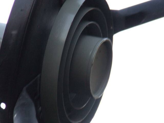
Finally getting back to my 10' mesh dish install that I started in June. Winter is coming and I want some good signals coming in by then. Taking photos as we go along and will post some soon. Right now I am puzzled by the DMS BSC421 LNBF that I am installing to replace the old chapparal LNB. The bolts holding the scalar ring to the feedhorn support tubing are bigger than the threaded holes in the new scalar ring for the LNBF. It did not come with any new bolts and the hardware store is closed until next week. Anyone know what size bolts are used on these things? 
C band LNBF install
- Thread starter rangergord
- Start date
- Latest activity Latest activity:
- Replies 18
- Views 7K
You are using an out of date browser. It may not display this or other websites correctly.
You should upgrade or use an alternative browser.
You should upgrade or use an alternative browser.
- Status
- Please reply by conversation.
Register to hide this ad
They are most likely metric, and it would be best to take it with you to the hardware store as they could be any random size
I have used the Chaparral scalar rings with LNBFs several times, you might try that.
Sometimes the LNBF tube is a pretty loose fit so you may need to shim the tube to the ring opening.
edit: yes, what Anole said.
Sometimes the LNBF tube is a pretty loose fit so you may need to shim the tube to the ring opening.
edit: yes, what Anole said.
Anole, the old scalar is integrated with the waveguide and LNB so the new LNBF cannot be attached.
I have used the Chaparral scalar rings with LNBFs several times, you might try that.
Sometimes the LNBF tube is a pretty loose fit so you may need to shim the tube to the ring opening.
edit: yes, what Anole said.
Is there more than one design of chapparal LNB ? My old scalar ring is casted into the waveguide and vert/horiz. switch and then attached to a C band LNB downcoverter.
Last edited:
I assume that's a very old style.
Dont hear about 'em often.
Pretty much everything in the last ... 15? ... 25? years, has used a separate rremovable scalar.
.
I'm going to bet you need M8 screws, But that's just from memory.
Dont hear about 'em often.
Pretty much everything in the last ... 15? ... 25? years, has used a separate rremovable scalar.
.
I'm going to bet you need M8 screws, But that's just from memory.
I have a few of those feedhorns with the integrated scaler ring. These were made specifically for the dish they came with as the fixed ring is set for that particular dish focal depth. These parts now reside in my unused satellite parts box somewhere in the storage shed along with several LNAs and down converters. The good old days!
The newer Chaparral scaler is made much better than the ones that come with the LNBFs that I have here, but if you don't have one of those the one that came with the LNBF will work fine. Place the LNBF in approximately the same position as the old feedhorn/scaler combo, or you can measure the dish and go by the numbers on the side of the new LNBF. This adjustment is not quite as critical as the feedhorn placement at the dish focal point. I have some spare bolts that would likely fit your LNBF but they are here and you are there... I am sure you can find them locally.
Good luck!
Got bolts,got nuts,got a drill ?Drill out the holes and make it fit.Got a tap and die set?Retap the holes for the bolts you have.Just because they made it that way doesn't mean you have to do it their way.
I have a few of those feedhorns with the integrated scaler ring. These were made specifically for the dish they came with as the fixed ring is set for that particular dish focal depth. These parts now reside in my unused satellite parts box somewhere in the storage shed along with several LNAs and down converters. The good old days!
The newer Chaparral scaler is made much better than the ones that come with the LNBFs that I have here, but if you don't have one of those the one that came with the LNBF will work fine. Place the LNBF in approximately the same position as the old feedhorn/scaler combo, or you can measure the dish and go by the numbers on the side of the new LNBF. This adjustment is not quite as critical as the feedhorn placement at the dish focal point. I have some spare bolts that would likely fit your LNBF but they are here and you are there... I am sure you can find them locally.
Good luck!
Thanks, I got 6mm metric bolts that fit the threads today. I will measure where the old LNBF was in relation to the new and set it there for now. What about skew?
... What about skew?
If your dish is motorized skew is set to zero (the motion of your mount automatically skews the dish as it travels the arc).
If you are setting up your dish fixed on a single satellite you will skew the feed for that particular bird.
Best to find your true south satellite and get the signal maxed on a transponder close to the middle of the band (around 4000MHz) and then peak the signal by slowly turning (skewing?) the LNBF in the scaler. Sometimes you can go between setting the skew and peaking the declination/asimuth several times before getting it zeroed in. Once you get a center transponder peaked check the others. I think all the antenna orientation on sats are within 10 degrees of where thay should be (on C-band only that is), so there can be variations between sats and TPs as you move from one satellite to another. Your antenna skew will line up with the satellite's antennae due to the movment of your mounting system.
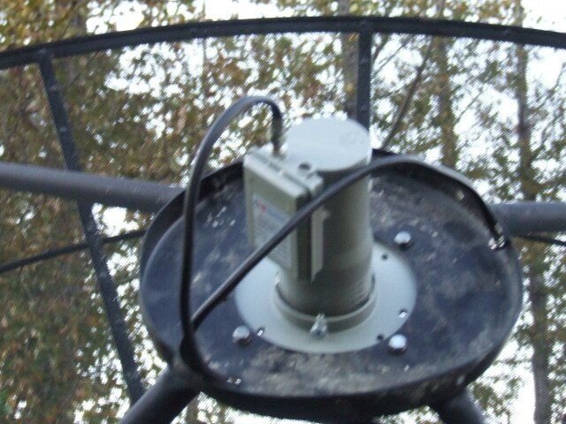
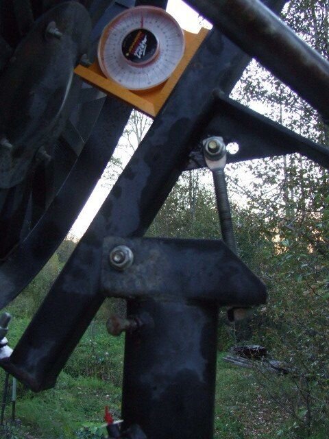
So here is a picture of the new LNBF. I measured the distance from the back of the scalar ring to the front of the LNB on the old integral chapparal. Then I measured the same on the new LNBF. I used an inclinometer to adjust the skew to horizontal or 0 degrees to the right. You can see there are two coax cables installed. One is a long one with one coupling splice in it that goes to the house. It is just over 150 feet long. The other is a short one piece coax cable for doing the initial dish setup with a portable TV next to the dish.
Attachments
Attempting to set up the elevation here but I am bit confused. I read in one place where it said that the elevation should be set at your lattitude in degrees. I am at 55.7 degrees N lattitude so thats where it sets at the moment. The confusion comes in reading my customized dish aiming coordinate tables. I entered my location in satellite AV's geosatfinder and printed off the tables. I have a potential view of 57 satellites and the one directly south is 121.00 W Galaxy23/echostar9 The true azimuth is 179.2 degrees and the dish elevation is listed as 26.50 degrees. This seems far too low for the main elevation setting. ????????
Attachments
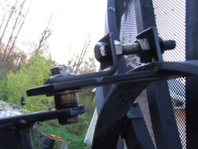
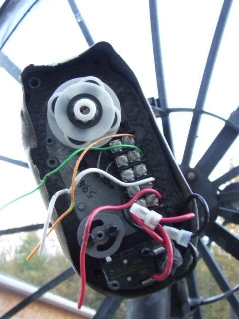
Finally the actuator is ready to be connected to the actuator control cable. I have put a splice in the old cables. I soldered the spliced wires and shrink wrapped them to hopefully exclude any moisture. Hoping it works. I have the red and black motor wires figured out but the green and brown? orange? Yellow? wire is puzzling. The wire is faded and is actually all three of the latter colors. The inside of the cover of the actuator motor case has the following notations
Brown-
Reed Sw
Brown-
Thats it. So is the wire brown or orange because I have both wires in the cable. What are the polarity of the sensor wire terminals? My V-box has red and black terminals for the two sensor wires.
Brown-
Reed Sw
Brown-
Thats it. So is the wire brown or orange because I have both wires in the cable. What are the polarity of the sensor wire terminals? My V-box has red and black terminals for the two sensor wires.
Attachments
It doesn't matter on the reed switch what color it is or what terminal you hook it to.Just as long as you have 2 wires coming from the switch hooked to the sensor terminals on the vbox.Just do NOT hook the reed switch to any power terminals,it is just a switch either open or closed.
If when you hook up the motor wires and the dish moves in the wrong direction,just swap the wires.
Oh and just to add it doesn't matter what color wires you use for the switch,just use the same 2 wires at BOTH ends.
If when you hook up the motor wires and the dish moves in the wrong direction,just swap the wires.
Oh and just to add it doesn't matter what color wires you use for the switch,just use the same 2 wires at BOTH ends.
- Status
- Please reply by conversation.
Similar threads
- Replies
- 9
- Views
- 330
- Replies
- 8
- Views
- 1K
- Replies
- 16
- Views
- 1K
- Replies
- 5
- Views
- 912


