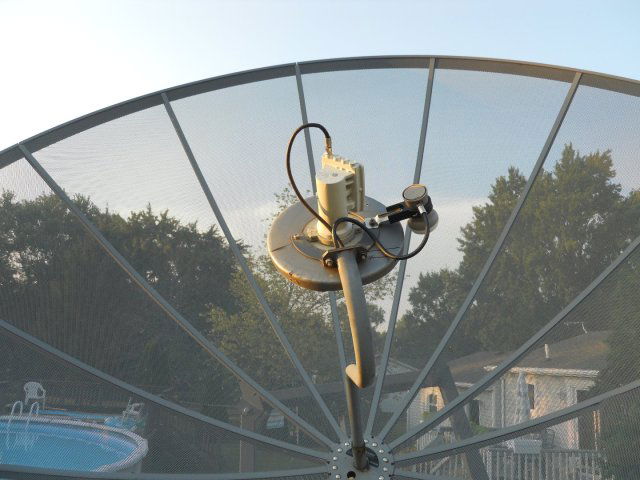
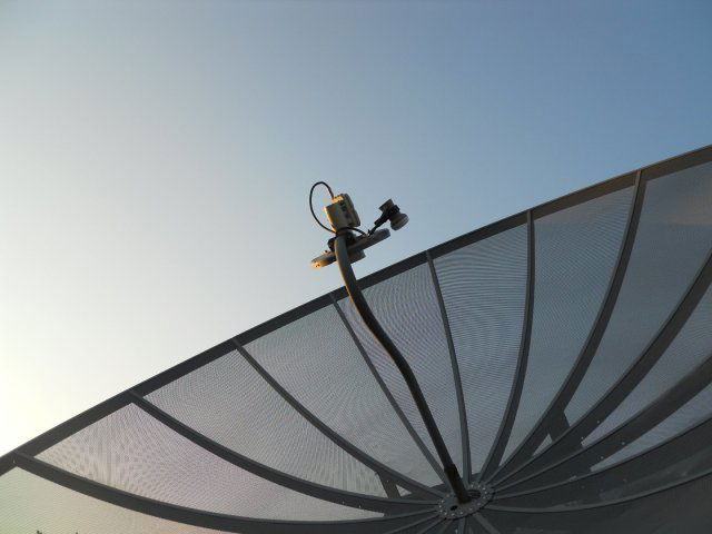
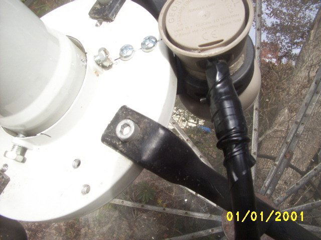
Proof Of Concept today! Ku Band Side Car on a C Band dish for under $30. I have been wanting to try this for some time, and today i finally did it. Thanks to LEEHRAT and arlo for the inspiration, advice, and the pictures. I am using a 10 Ft Winegard Pinnacle BUD and an Amiko Mini HD265 FTA Receiver. For the Sidecar Ku LNBF i am using a GeosatPRO SL1PLL as recommended, and IT IS WORKING! Also using a Universal Single LNB Bracket for the Mount. So far tonight i have scanned in all the Channels on Galaxy 19 97.0W Ku and also scanned in channels on Galaxy 16 99.0W. So i am tracking the ARC, but I am not 100% dialed in yet. A HUGE problem is that the dish is way higher than my ladder can handle at True South (83.0W) so my minor adjustments are difficult and time consuming to do. I am 6 Ft tall and standing on my 6 Ft ladder i can not reach it. So I have to move the dish all the way East to work on the LNBF, make adjustments etc..., then move it back West again to check my results.
I KNOW my Ku LNBF is pointing way too far out from center. From reading this thread i realized you dont want to point it right to center on a dish like this with a Button Hook with a Center Plate in the middle. I started like that and i could find no signal whatsoever. So i moved the angle of the KU LNBF out from center to illuminate a larger circle on the mesh and Bam - i got signal! But i moved it to far out from center. To put it into perspective 97 W C Band for me is at count 886 on my dish mover. For Ku Band on 97W with this set-up its at 963. That is where 89.0W would be on C Band for me. So i think maybe i can move it in for a better signal. But not tonight, i am tired and satisfied with my results for now. So lots of work to do but i can say this works, and i am very excited to get it dialed in. I will update as i go.
Glad to read you're making progress.
I attached a sidecar to my 8 foot solid dish several years ago and it's performing very well.
At Titanium's suggestion, I used a pipe hanger, slightly modified to attach my kU lnb, with great results. Most of the signals on 97w for example, come in slightly above 12dB.
This would be consistent with the data in my attachments earlier in the thread. A 3 m reflector should have about +49 dB of gain at Ku. A 1 m reflector should be in the +38 to +39 range. I would think at least -10 dB down from the peak by being off the boresight should be expected.
I tried the exact same setup in my 10ft mesh C band dish. Added a KU- side LNB.
No luck catching any signal. I cathched ~40% signal quality only if I keep the KU lnb directly under the C band LNBf.
Do you catch the same satellite in both C band and Ku band?
I tried the exact same setup in my 10ft mesh C band dish. Added a KU- side LNB.
No luck catching any signal. I cathched ~40% signal quality only if I keep the KU lnb directly under the C band LNBf.
Do you catch the same satellite in both C band and Ku band?
not simultaneously... since the Ku LNBF is mounted to the side, its aim will be different than for C-band. Usually the difference is about 6-8 degrees depending on the dish size and C-band scalar diameter.
What is absolutely critical is that the Ku LNBF and teh C-Band LNB feed be in the same plane that is perpendicular to the polar axis of the dish mount. Also it should be fine tuned (it's very sensitive to misalignment)
Reduced illumination: agreed.
Illumination angle of a normal Ku LNBf for an offset dish would be about 75 degrees (based on e.g. the Triax 115 dish), I guess, so equivalent to an f/D of about 0.75.
Compare it to the f/D of the PF dish, and you can calculate what diameter of the dish is "seen" by the LNB.
Numerical example:
When you have a PF dish with f/D=0.31 (width=100, depth=20), and LNB feedhorn with f/D-equivalent of 0.75:
Effective.diameter = ( Diameter.of.PF.dish * 0.31 ) / 0.75 .
Outcome = Diameter.of.PF.dish * .41,
so just over 40% of the width of the PF dish.
So that example value matches your value, in the quote above.
I am afraid I cannot follow the rest of your post, and I'm not sure what all these 2 degree compliance documents have to do with multifeed effectiveness?
The documents seem to have to do with beamwidth, sidelobes, and interference from neighboring satellites. I didn't find anything about multifeed, by superficial reading?
With my link above of the Triax dish, I came to 1 dB loss for a 10 degree off-axis-mounted LNB.
I believe that is congruent to the practical experience by users of multifeed setups.
Just from being off-axis I cannot imagine such a steep penalty.
The only thing I can think of that would cause a steep penalty in gain, is aiming an LNB not at the satellite, but at an angle left or right (off-axis) from a satellite. But that is not what is done, with a multifeed setup.
However, it can be confusing, when it is not clear whether the terms "off-axis" or "boresight" in case of a multifeed setup, are defined relative to the dish's axis, or relative to the aiming direction ("axis") towards the satellite.
So, am I missing something?
If yes, what am I missing?
The data in the PDFs illustrate both the ITU and NTIA requirements from four decades ago for antenna designs to be able to select satellites spaced at 2 degree separation. This is in order to receive a signal without co-channel interference from an adjacent satellite, but more specifically to allow an antenna to transmit and not cause interference to other users. In RF theory, this is reciprocity. For the same frequency, an antenna's performance for RX and TX should be the same on paper and very close in reality. The roll-off graphs show the maximum signal strength allowed in order to maintain 2-degree compliance. The graphs start at 1 degree off the boresight. This is important because 1 degree to the left and 1 to the right is 2 degrees (a.k.a. starting at 1 degree on the graph is not arbitrary or "magic").
For a 3.0 m reflector, the gain is roughly +40 dB for C and +49 dB for Ku. The -3 dB beam widths are 1.75 and 0.55 degrees, respectively. At that beam width, you have lost half of your signal strength. The ITU/NTIA calcs are based upon ratios of diameter and the signal wavelength in use. For our purposes, to hit the 2-degree requirements, the resulting equation is "29 - 25*log(theta)". The equation can vary based on a couple of factors, but we will use this to ilustrate the point. Even if we used "32-25*log(theta)", the results are still range-bound.
For Ku, if the gain is +49 and the beamwidth is 0.55, then at 0.55 degrees off the boresight, the gain is +46. From the equation, at 1 degree off the boresight, the maximum gain allowed in order to be 2-degree compliant is "29 - 25*log(1)". The log of 1 is zero, therefore the max gain is 29 dB. As a result, we essentially have a -3 dB drop in the first half of a degree and another -20 dB drop in signal strength in the next 0.5 degrees. That is 1/100th the signal strength when you are 1 degree off the boresight. That is the signal falling off of a cliff. Even a 0.7 m elliptical is still around +37. At this point, if the anecdotes are that adjusting the focal length positioning of a C or Ku LNB can tweak the signal strength 1 or 2 dB, those values are rounding errors when compared to the roll-off values.
We have very differing commentary throughout the years on this site and others about the performance of Ku side car LNBs. There are some talented people who can make it work and there are some talented people who cannot make it work. Skills being considered equal, the only logical explanation to me is that some people have 2-degree compliant reflectors and some do not. I will suggest those who cannot make the side car work probably have compliant antenna systems, while those can make it work do not have compliant reflectors. If we take the anecdotal "it makes a 10-foot dish perform like a 4-footer", that means the effective gain needs to be around +40. If the side car is located 6 inches off the boresight on a reflector with a 48 inch depth, this corresponds to arctan(6/48) = 7.1 degrees. At 7.1 degrees, the maximum compliant gain is 29 - 25*log(7.1) = +7.7 dB. This is approximately -41 dB lower than than the peak, essentially 1/10000th the signal level. This is how antenna systems designed to the 2-degree criteria can discriminate between adjacent satellites. The roll-off has to be that steep.
For your Triax, I will assert that the mechanical equation and associated physical design of the reflector has multiple focal points that where the signal intensity is such that a lock is achievable. For me, it reasonably follows that the reflector design cannot be 2-degree compliant. If the roll-off graphs were followed, you wouldn't be able to lock on those adjacent satellite positions. I can play side car games with stamped 1.0 m metal reflectors that are a bit more challenging with my 1.0 m fiberglass Channel Master that are almost impossible with my 1.2 m TX-compliant Prodelin VSAT reflectors. I am willing to be that no side cars would work on my client's 4.5 m VSAT earth station antenna. They already get calls from the Eutelsat NOC when one of the remote BUCs runs consistently hot on its TX power because the operator is so concerned about interference on their own satellite, nevermind to adjacent satellites.
In the 86-196 PDF, the authors say in Section 2.1 "There are numerous companies that design and manufacture the smaller diameter (3 to 6 m) antennas that exhibit a wide range in the quality of performance... Some antennas are manufactured without the benefit of a full range of technologies and facilities necessary to achieve a high quality product... Performance tradeoffs often favor low cost rather than high quality. This compromise is especially common in the highly competitive, low cost, high volume production type of antenna... In the design of larger and more expensive antennas, such as INTELSAT Standard A and B antennas, performance has generally been more predictable and in line with specified sidelobe envelopes." Those observations were written in 1986. From my standpoint, Section 2.1 is very illustrative and I believe the points have continued to be true through the decades.
Aside, today I was given some old Chaparral prime focus Ku feeds with scalar rings and some 4-leg mounting plates sized for the Ku scalar. They were used to retrofit C band reflectors to be able to receive Ku Star Choice here in Canada. The scalar would press-fit into the mount and used no additional fasteners, so it could only be adjusted "so much". It is definitely not "magic". At this point, I really want to get my salvaged 3.0 m antenna up to do some hands-on investigation.
Mea culpa corrections on some arithmetic and associated wording...
Beam widths are 1.75 and 0.55 degrees. -3 dB point will be at half of that, so 0.875 and 0.275 degrees on either side of the boresight. As a result, the drop on the gain figure is even more steep than illustrated above. The equation is for any particular angle on either side of the main beam. As a result, figures like "7.1 degrees" are left or right on the main beam and do not represent a beam width... it's just the value at a particular off-axis point.
Look. You can bury yourself in all of the nomenclature. Get Torettes. Read it again and again.
Hypercasey choose to reflect West and on the same side of the ku lnbf mounted to the scalar.
If you do have a buttonhook feed, you're going to get reduced signal because of all of the "junk" in the way.
Because your lnbf is on the side of the scalar, expect a bit of offset. So a c band sat peaked for signal may have the ku signals peaked a touch East or West.
It is a quick, easy, and cheap way to get ku reception.
Realize though. Because they are designed for ~ 2 meter or so dishes. That's about all of the illumination you're going to get even on the 12 footer I have.
They are (I believe) designed for offset dishes also. So accepting that and reflecting at some angle other than dead knutz at the center may (did for me a whole lot) give the best signal. Buttonhook feed or perimeter feed support arms.
Try a bit of experimentation. Toss the pile of paperwork away.
Do an offset. Bounce the lnbf off of the center to semi-resemble an offset feed. Look at my photo.
Grab a signal. Get it peaked and note the dB of the signal. I mean get it peaked. Get out of the way of the reflector.
Like, get a c band signal peaked. If you know how many dish mover pulses (counts) add up to a degree. Shoot of 5 or 6 degrees of offset.
Or at first. Just a few. Get that ku lnbf shooting off-center.
5-6 degrees works for me because as I grabbed my first ku sat and peaked signal. Moved that Geosatpro lnbf all over the place to get the best possible signal. Made a bracket and put in a bit of adjustment.
5-6 degrees ended up the best offset from c band signals because after getting that first sig. peaked.
I jogged the dish E-W just a touch to see if the aim could be refined to get better signal. And I did.
Dead on with the buttonhook assy. in the way killing usable reflector efficiency. Forget about it.
3 degrees (estimate and verified by what it took to get back to a strong c band signal). Not enough.
5-6 degrees was the best. Out at 7-8 degrees. dB started to fall off and aiming to peek signal got "muddy". Like, a lot of dish movement either way was needed to get the best signal.
In c band and in your scanning menu. You ignore the ignore adjacent satellites by X degrees setting.
In this situation, ku band will benefit. You might scan a satellite and compare the transponders with charts and get many more that just don't make sense. Until you find out that the signal is a bit weaker and they actually belong to a neighbor satellite also.
Yeah..... kind of what I posted yesterday and still has me a bit confused. But, we'll get it!
I'll attach a cool little toy to let you animate and simulate using a parabola and moving the feed point all over the place.
Play with it. It's pretty cool and might give you an idea to better position a feed.
But. Toss that pile of paper away and forget about all of the garbage in it. Until you get the best possible signal possible.
I apologize that mathematics is so onerous. Like Barbie, we should all go shopping instead.
Unfortunately, the arithmetic is so boring and tedious that even the lawyers liked it and decided to codify it 42 years ago. Uncle Sam, say it isn't so!
Title 47 (Telecommunication) / Chapter I (Federal Communication Commission) / Subchapter B (Common Carrier Services) / Part 25 (Satellite Communications) / Subpart C (Technical Standards) / Subsection 25.209 (Earth station antenna performance standards)
Like seriously, what a way to wreck a party. Sheesh.
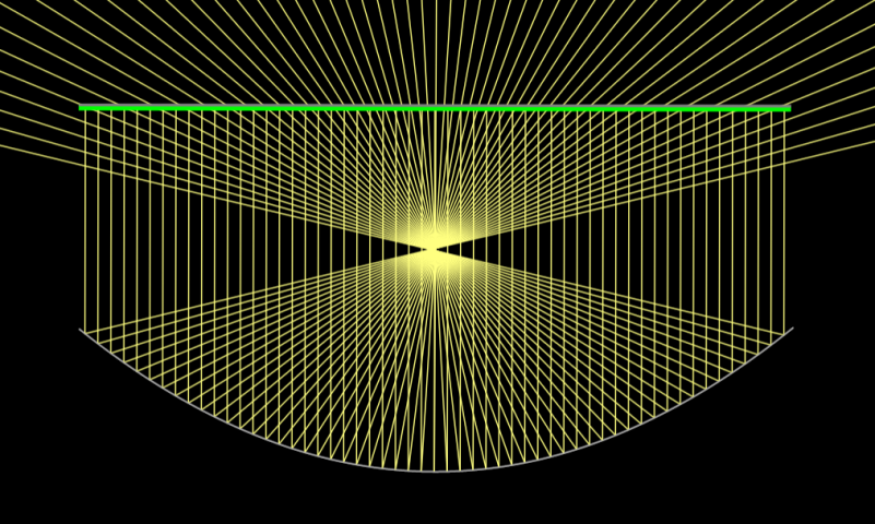
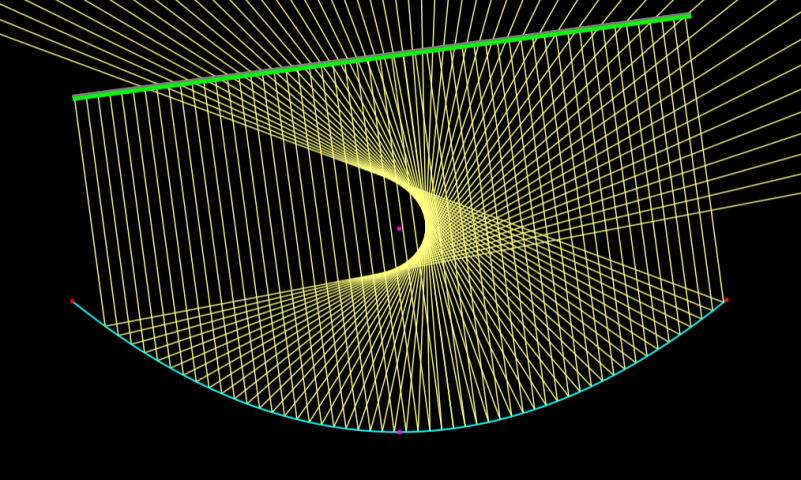
The ray optics ("applied math") simulator was handy to create the following images. First, we have a prime focus parabola with the focal point outside the reflector depth. Second, we have a prime focus parabola with a signal at an offset angle. I exaggerated the angle for illustration purposes. Whether the incident signal changes angle or the reflector changes angle, it is the same effect. The focal point changes into a crescent-shaped wavefront of varying constructive interference with an increasing void in between the wavefront and the parabola's natural focal point. This is the Ku offset LNB "where to position it?" issue.
The purple dot is the focal point. For a 2-degree reflector, the signal strength at that location is going to drop off at a previously-described mathematical rate. To the right of that wavefront? Well, one might describe the signal levels as "increasingly muddy".
In the offset image, only a fraction of ray merge immediately horizontally right of the focal point. That's the "4-foot effect". The efficiency of the reflector diminishes quickly when not at the focal point. Because all of the ray that converge at that location are source from points inside the dish, the angle of the Ku stepped conical scalar rings could be drawn in, further illustrating the concept of illumination limitations. It is also possible that removal of the Ku stepped scalar entirely might improve signal gathering. Hack saw exercises and experimentation are left to the reader.
Others have noted they are nudging the dish positioners sufficiently to be a number of degrees off the original target boresight. The point of that is to attempt to peak the wavefront. It has a point of diminishing returns because, well, you're now running essentially an offset reflector with gain parameters based on a parabolic mechanical equation rather than an elliptical equation. You aren't trying to hit a new focal point; you're trying to maximize a relative position in a goofy wavefront. Because we only use hand tools and not pesky math, we have to experiment with where to position the Ku LNB and how to adjust the reflector azimuth. <whisper> If someone wanted to know where to nudge their positioner, though, I would suggest that the arctan of (Ku offset from natural focal point / focal length) might be a good starting point. </whisper>
This is the illustrated HOW and WHY of antenna and offset LNB performance for prime focus systems. I apologize to all readers for using my 30+ years of experience in electrical engineering, mathematics, and RF regulatory filings for terrestrial microwave systems designed to five and six 9s availability. I will not derive anything from first principles again. I know that I have hurt many people with my HP RPN calculators and graph on log paper. I also apologize to all female techies for the joke. (Let's go shopping regardless.)
I apologize that mathematics is so onerous. Like Barbie, we should all go shopping instead.
Unfortunately, the arithmetic is so boring and tedious that even the lawyers liked it and decided to codify it 42 years ago. Uncle Sam, say it isn't so!
Title 47 (Telecommunication) / Chapter I (Federal Communication Commission) / Subchapter B (Common Carrier Services) / Part 25 (Satellite Communications) / Subpart C (Technical Standards) / Subsection 25.209 (Earth station antenna performance standards)
Like seriously, what a way to wreck a party. Sheesh.
The ray optics ("applied math") simulator was handy to create the following images. First, we have a prime focus parabola with the focal point outside the reflector depth. Second, we have a prime focus parabola with a signal at an offset angle. I exaggerated the angle for illustration purposes. Whether the incident signal changes angle or the reflector changes angle, it is the same effect. The focal point changes into a crescent-shaped wavefront of varying constructive interference with an increasing void in between the wavefront and the parabola's natural focal point. This is the Ku offset LNB "where to position it?" issue.
The purple dot is the focal point. For a 2-degree reflector, the signal strength at that location is going to drop off at a previously-described mathematical rate. To the right of that wavefront? Well, one might describe the signal levels as "increasingly muddy".
In the offset image, only a fraction of ray merge immediately horizontally right of the focal point. That's the "4-foot effect". The efficiency of the reflector diminishes quickly when not at the focal point. Because all of the ray that converge at that location are source from points inside the dish, the angle of the Ku stepped conical scalar rings could be drawn in, further illustrating the concept of illumination limitations. It is also possible that removal of the Ku stepped scalar entirely might improve signal gathering. Hack saw exercises and experimentation are left to the reader.
Others have noted they are nudging the dish positioners sufficiently to be a number of degrees off the original target boresight. The point of that is to attempt to peak the wavefront. It has a point of diminishing returns because, well, you're now running essentially an offset reflector with gain parameters based on a parabolic mechanical equation rather than an elliptical equation. You aren't trying to hit a new focal point; you're trying to maximize a relative position in a goofy wavefront. Because we only use hand tools and not pesky math, we have to experiment with where to position the Ku LNB and how to adjust the reflector azimuth. <whisper> If someone wanted to know where to nudge their positioner, though, I would suggest that the arctan of (Ku offset from natural focal point / focal length) might be a good starting point. </whisper>
This is the illustrated HOW and WHY of antenna and offset LNB performance for prime focus systems. I apologize to all readers for using my 30+ years of experience in electrical engineering, mathematics, and RF regulatory filings for terrestrial microwave systems designed to five and six 9s availability. I will not derive anything from first principles again. I know that I have hurt many people with my HP RPN calculators and graph on log paper. I also apologize to all female techies for the joke. (Let's go shopping regardless.)
Firstly the link is working with a true parabola. My higher education was squelched after high school. That's another story for another time.
I didn't wreck the party. I brought the Jager AND the weed. When needed I really love reading textbooks with theory.
Just that, well, when verbiage in one paragraph leads to the next half of the page with algebraic, calculus, the Greek symbols. The things you see in the movies where the geeks are up on ladders in front of a huge blackboard with chalk and white sleeves used as erasers.
Not my forte'. Education and knowledge is awesome. But all of the math in the world in one shot, in a stack of documents.
In that world. Men would have been on the moon in 1964 in a rocket that launched perfectly the first time. And nobody would have died in the process. All of the engineering degrees and sheepskins on the wall could not attain that.
I like the Nike approach. Just do it. With a bit of background, of course. People hate Elon. Well, Elon didn't do it. Him and his well picked team did it. Right?
A Chaparral feed with polorotor, a feed with four independent flanges for two c and 2 ku band rf amplifiers integrated that utilizes a single microwave waveguide would be the correct and only apparent way to achieve the desired "
I want to add Ku Band to my Cband Dish
" in a book-proper way.
So, a dude spends a gazillion bucks and does it proper. And finds out that ku-band simply......sucks.
He already has a very good working c band setup. 10-20 bucks and some elbow grease. Ba-Da-Bing!!
That's all I'm trying to get across.
True parabola. The only one I was taught in school. If it's not true, it ain't a parabola. And the rules apply.
The simulator just let's you play around to see what happens if you change offset angles. Or like Hypercasey did, which I like, DON'T shoot over the center and use the same side of the dish for the offset.
And, as mentioned. I DID remove the first "step" in the ku lnbf. With minimal, if any at all, signal improvement.
Thinking that doing it would increase the illumination angle. If that's the correct terminology that is in "The Book" for which I briefy skimmed over.
Stacks of paper ain't-a- gonna' tell you to slap that baby there and it will work like a peach.
Same for me with my aged dish.
Direct c/p:
Focal length = f
Depth = c
Diameter = D
f = ( D * D ) / ( 16 * c )
Well. Discussed before somewhere here in the archives. I got Mr. Rusty set back up after years of setting.
Got an lnbf from Brian, a receiver from somewhere.
Did the math. Slapped the feed and scalar exactly where the math said to. I mean exactly. I like fabricating and building "stuff" to sometimes exacting measurements, tolerances. This is not a NASA dish. It was probably made from some yaznooks in an old sawmill with a plaster of Paris mold and fiberglass and metal sprayer like is used to build up worn bearing surfaces prior to re-machining.
But it works!
AFTER playing around with the feed distance and scalar distance.
See the guy wires? Railing turnbuckles to fix sag from years of just setting at zenith so my old man could mow the yard.
3 strings across the face showed around on-eight's inch separation. Found what it took to make it nil.
Fixed it. The polar axis sag. Tighten the turnbuckle to remove guy wire slack at the 4 o'clock position.
The noon guy is static currently. Set to just slightly tension it.
Adjust the third turnbuckle to just take up the slack.
After first boresighting the feed and making sure the scalar was equidistant from the dish edges and parallel to the face.
The polar axis turnbuckle tightened...maybe....3-4 turns boosted signal from in the 11 dB range to 14 dB. Other c band tp's floor my osmio4k at over 18 dB.
Did I do good? Pg. 481, section 3, paragraph two.
In the real world, the "books" would say "Toss it, it ain't no good". Am I, will I, did I? The authors are enjoying some real yellow and nasty-tasting Wheaties right about now. Right about now, the funk-soul brother. Lol.
Me? I ain't touched, phased. I had and still do respect good mentors and teachers. I really wish I had the opportunity for higher education.
Then you have people like Charlie Kirk saying higher education in the 2020's is a farce. Companies are hiring talent in lieu of 8 year university grads with so many degrees that they can't even change a toilet flapper or change a tire.
I disagree. RPN? A slide rule? Just a few minutes with them out again and I'm there, dude.
You have to agree though. Typing in "Online <choose your topic> calculator, simulator" is really, Really cool.
I think I illustrated above, that this is mainly the consequence of the mismatching illumination angle of the LNB-feedhorn towards the opening angle of the (PF) reflector.
Do you agree to that?
The data in the PDFs illustrate both the ITU and NTIA requirements from four decades ago for antenna designs to be able to select satellites spaced at 2 degree separation. This is in order to receive a signal without co-channel interference from an adjacent satellite, but more specifically to allow an antenna to transmit and not cause interference to other users. In RF theory, this is reciprocity. For the same frequency, an antenna's performance for RX and TX should be the same on paper and very close in reality. The roll-off graphs show the maximum signal strength allowed in order to maintain 2-degree compliance. The graphs start at 1 degree off the boresight. This is important because 1 degree to the left and 1 to the right is 2 degrees (a.k.a. starting at 1 degree on the graph is not arbitrary or "magic").
So I read your ITU documents a bit more thorough, and they are indeed about interference of neighboring satellites (your "2-degree compliance"), not about multifeed setups.
Do you recognize the difference?
In a multifeed setup, to receive a noncentral satellite, the feedhorn is displaced from the focal point at the center of the dish to the 'focal cloud' of the non-central satellite.
All these 'interference' articles assume the LNB feedhorn stays at the focal point of the dish.
To me it looks like you confuse the one with the other.
For your Triax, I will assert that the mechanical equation and associated physical design of the reflector has multiple focal points that where the signal intensity is such that a lock is achievable.
The Triax TD Unique indeed is a multifeed dish, with 0 dB loss over the range from -13 degrees to + 13 degrees (see graph).
The just "1 dB loss for a 10 degree off-axis-mounted LNB" is for the Triax TD78 (see the same graph).
This is because of some sorts of abberations, as they are called I believe, for the reflection of a parallel beam on a paraboloid reflector with the beam not along the symmetry axis of the (mother) parabola.
[ The interesting thing here of the focal cloud being shifted away from the focal point, is the beam deviation factor (BDF), I think, which according to literature is about 0.9 for common satellite dishes. I've never found equations that came to that outcome though, though I might have made errors. And I wonder if (or how much) the BDF in the offset dimension (in case of an offset dish) is different from the BDF in the non-offset dimension.
I've made my multifeed-skew (or multifeed-tilt) calculator with the assumption, that they are (about) equal. ]
I have no experience with PF dishes, or C-band, though. But I've learned quite some things about the geometry of (paraboloid, spherical, toroid) reflectors and multifeed calculations, I would say.
Sorry for the delay. A bunch of "real life" got in the way over the last few weeks.
A number of ideas did not make sense to me from an engineering perspective, so I did a bit of a deep dive because I knew there had to be better explanations available out there.
As it turns out, there is a plethora of information available dating back over four decades and in some cases, back upward of six decades. When commenters in other threads have mentioned "2 degree compliant dishes", there is a lot of information available from ITU and NTIA sources to explain the derivation of the parameters. Long story short, anyone having experiences with offset LNBs with minimal changes in gain is likely either using a reflector that is either not designed to 2-degree-compliance or is using a reflector that is capable of capturing signals from multiple satellites. Between ITU REC-465 and ITU REC-580, there are side lobe envelope definitions that are the minimum technical requirements of an antenna design to provide protection against signals that are not on the boresight. By electromagnetic reciprocity, the transmit and receive functions of an antenna design should be largely the same, so determining the parameters around a TX-certified design should get the reader into the realm of a TVRO design pretty quickly.
A33: Specifically above, the fixed, stepped, conical scalar design for Ku offset dishes is meant for a different f/D ratio reflector. The placement of the LNBF on a PF reflector based on the offset scalar design f/D ratio would not have that element not at the PF focal point. Using a C120 flange Ku LNB with a flat scalar would, hence the "focal length disparity". From my standpoint, the f/D "disparity" is really just due to the scalar design grafted onto the LNB.
Looking at the various attachments and seeing the theoretical and empirical graphs, it becomes more clear to me that the performance of an offset Ku LNBF on a 2-degree-compliant reflector is going to be partially influenced by the scalar design as well as the offset angle. "A Ku LNBF offset on a 10' prime focus antenna performs like a dedicated 4'" statement starts to make a bunch of sense.
In the past, I have mentioned that C and Ku performance can be approximated by looking at a similar diameter reflector used for terrestrial microwave. I now believe that to still be true, but with the major caveat that, once learning about "32-25*log(theta)" and "29-25*log(theta)", the terrestrial antenna designs are much more conservative. Practically all microwave antennae in the last three decades are "high performance" and include a shroud that is essentially a sidewall that is the depth of the antenna edge through to the height of the feedhorn. You really cannot purchase a microwave antenna for use in the western world that does not have an integrated side shroud. And that shroud acts basically like a scalar in that off-axis signals are attenuated or outright blocked, hence the greater selectivity and discrimination on the radiation plots. Once I recognized this because of the need for hyper-reuse of terrestrial channels and that satellite reflectors rarely have any perimeter "fencing" and after analyzing the mid-1980s NTIA docs, it all started to become very clear to me.
For the interested, please take a look at the attachments.
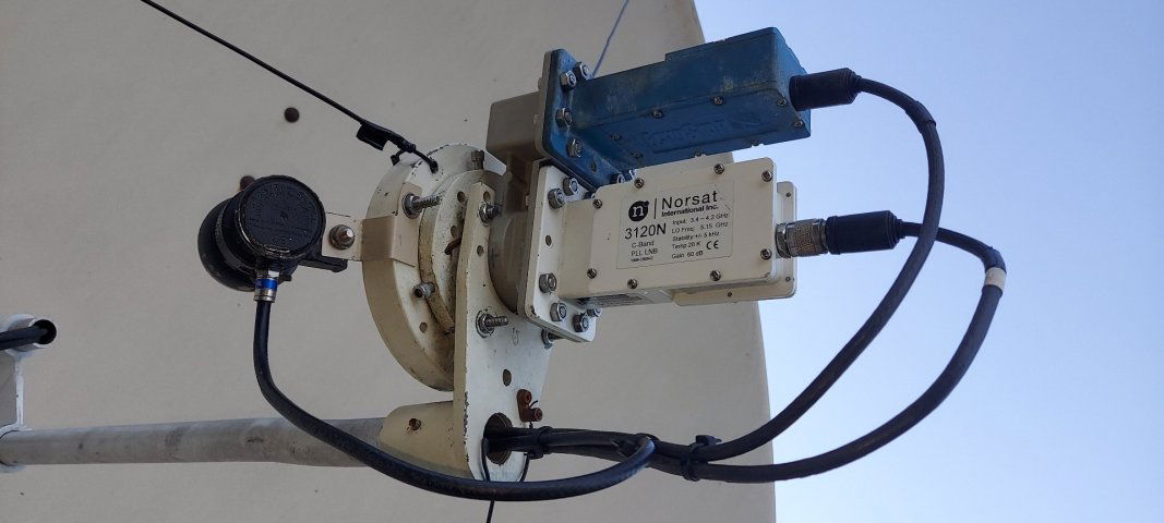
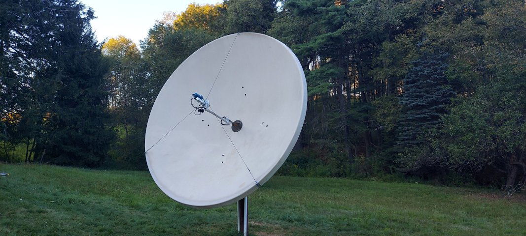
I am getting a 10-foot dish working that was on our property when we purchased. Got the C-band working quite well using a Titanium LNBF and a FTA receiver AMIKO mini 4k. I have read the numerous posts to add a KU LNB which I have done but am not sure if it is is the right spot. We mounted it due west of the CB LNB when the dish is pointing straight up (due south).
Please ref the photos. Also the skew is in line with the CB LNB.
We are at 27.236N -82.506W
So is this the right spot? I realize the the KU signals will not be received on the same satellite as when getting the CB...
However since then a couple of hurricanes dislodged my KU LNB and just now I am getting to fixing everything. I am not have much luck with the alignment.
Here is my question. I did just buy a combined C/KU lnb and got the C band working but the unit does not have the 5G filter making the channels unwatchable. Thus I never even tried to get the KU working. I want both.
So instead of doing the sidecar method of adding KU, I cannot find a combo lnb with C/KU with C band 5g filter built in. This would be perfect in that one only has to aim the dish once to get both bands.
Can someone tell me where to get such a LNB. Does not seem that they are made!
A combo lnbf was also an interest until hearing of the poor performance of them in comparisons and reviews. So no big surprise nobody is making a filtered new unit.
You could probably go with an old Chaparral feed but would need a dish mover with polarity control. Or an ancient ebay receiver/dish mover with polarity control built in. You'd have to get up to change settings.
Or an orthomode feed for 2 c & ku lnb's. Did anyone say $$$? Plus the multiswitch and diseqc switch involved.
Do the sidecar. If you do it right. You may not get the same satellite in both bands. But you could aim the ku to be spot on 6 or so degrees East or West from it. Depending on the side you mount it on.
Thanks for the replies, I did have the sidecar working a few years ago but last year hurricanes Helene and Milton took care of that. So I am starting from scratch to get the KU lnb aligned. We will get there as this is a hobby so not the end of the world.
Thanks for the replies, I did have the sidecar working a few years ago but last year hurricanes Helene and Milton took care of that. So I am starting from scratch to get the KU lnb aligned. We will get there as this is a hobby so not the end of the world.
For me make sure your dish is pointed at true south, then I put the ku at 90 degrees and mine is about 4 degrees from c location, exp 99 c would be pointed at 103 k. I have attached picture of my set up