Actuator Sensor Types

  • WELCOME TO THE NEW SERVER!

    If you are seeing this you are on our new server WELCOME HOME!

    While the new server is online Scott is still working on the backend including the cachine. But the site is usable while the work is being completes!

    Thank you for your patience and again WELCOME HOME!

    CLICK THE X IN THE TOP RIGHT CORNER OF THE BOX TO DISMISS THIS MESSAGE
Status
Please reply by conversation.

signal.quest

SatelliteGuys Pro
Original poster
May 29, 2009
176
0
Near Scranton, PA
I have not been able to get on the roof to determine my sensor type or cabling color function. I do have 3 sensor wires and my actuator is old. Can I safely assume it is a Hall sensor?

Is it OK to use a Hall instead of replacing it for a reed? What is the benefit of the Reed? Is it more accurate? Can I supply 5V to the Hall by guessing which is the correct wire or is that dangerous for my G-Box or sensor? I also have an old Analog receiver that accepts 3 sensor wires. Should I use that to figure out what the cabling setup is? Thanks.
 
Hall got more pulses per move than Reed.

It's not good trying to find the +5V line, you could fry the sensor.
 
IMHO it's not safe to assume anything. Use a meter to find the +5v source so you know which is which. On two of my 3 receivers the +5v source is labelled as such on the back panel.

As far as which is better for this application, that one is a toss up. My 8500 RPM race engine uses Hall sensors for both drive shaft and engine RPM measurements for the data logger and I'm pretty sure that a reed switch wouldn't operate at that RPM due to mechanical limitations of the switch itself. Most all the newer movers have reed switches and some with counts as high as 60 counts per inch without any apparent problems. Truth be known, reed switches are used because they are a) simple (2 wire hookup), b) cheap ($3) and c)relatively accurate at the RPM these output shafts turn at.
 
I wish I knew the hall sensor lead that was expecting 5v. I don't feel like going up on the roof in this weather to take the cover off the actuator.
 
Hall effect transistors don't bounce. Reed switches tend to bounce. more the older they get, And worse if only just in the magnetic field. Reason to get them close to the magnet wheel. That's usually why recalibration is needed occasionally.
There is another type, Optical. Uses a LED, mechanical interrupter(wheel with slots) and a photo detector transistor. This also requires a 5v source.
Yes, you can use a Hall, or Optical. Just have to supply 5v dc from a regulated power supply. Wall plug-in style should work just fine. Negative connected to the negative or ground of the sensor connection of the mover.
How are you moving the dish now, doesn't the mover have a 5v connection, with the pulse and ground?
If not, there is no other way to know, but to open the actuator up and look see.

Forgot about the 10 turn pot. That ain't gonna work with the new equipment. Must be changed out.
 
Last edited:
can you see a name on the actuator, then google it and that will probably give you all the info on the actuator, far as I know, the pot type sensor was used on the very first 'C' band systems and those are long gone, I think the reed sensor would be most common and it only needs 2 wires, if I remember correctly, I only saw hall sensors on actuators with the name 'Uniden' on them of course there may be others that used hall sensors and maybe a few 'oldtimers' out there could add their experience
 
I have attached a pic showing the label as a Superjack. Did they all use the same type of sensor?
 

Attachments

  • DSC01486.JPG
    DSC01486.JPG
    385.5 KB · Views: 276
From my experience, I can say that they may all look very similar on the exterior, but can be quite different inside the cover. Only 2 to 4 screws, usually, to take off the cover and look see.
 
If that SuperJack has a reed switch then there will likely only be two wires connecting to it. I just recently replaced mine and those wires are black and gray and those switches are available online for about $12 + the ride.
 
Ok. I was able to remove the cover and take some pics. I think I have a REED switch since I only have blue and grey wires for sensor. Can someone please confirm from my attached pics. I also took pics of the schematic inside the cover. I would like to adjust the actuator to extend it's reach as much as possible. Can someone tell if I have the ability to adjust it further from the pics? Thanks as always!
 

Attachments

  • actuator.JPG
    actuator.JPG
    707.3 KB · Views: 308
  • sensor-wires.JPG
    sensor-wires.JPG
    435 KB · Views: 253
  • schematic.JPG
    schematic.JPG
    2.5 MB · Views: 265
:eek: 
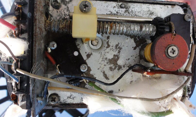
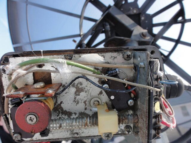
Man, I'd say your weather seal isn't sealing. From all the rust and other assorted crap in there I'd start looking for corroded wire connections first!:eek:

FYI, the SuperJack I have on my SAMI dish doesn't look anything like that so I can't help with the adjustment thingie! :confused: Sorry. I'm sure someone here has worked with one of those though.
 
Thanks for responding with the edited pic. From your diagram if I adjust the limit to the right it increases the reach? And to the left would decrease the reach?

When I removed the cover, water came out. How do you recommend I seal it? If my reed switch is damaged where did you buy the replacement?
 
When I removed the cover, water came out. How do you recommend I seal it? If my reed switch is damaged where did you buy the replacement?

You can seal it on the outside with clear GE RTV after you put the cover back on it. Main thing is to make sure the arm is mounted with any openings pointed down so water can't run up into it. The wires on my SuperJack come in from the bottom so there's no way for water to run up hill.

But first thing I'd do is to try to make sure that corrosion isn't the cause of it not working. Disconnect the wires one at a time and clean the connections with a small wire brush that you can find at your local hardware store. I've got one that looks like a tooth brush only the bristles are stainless steel. Once you clean it up then it might not be a bad idea to coat them with some silicon grease to keep moisture out in the future.

That reed switch doesn't look anything like the one I bought online. I did buy one that looks "similar" to yours from DigiKey but it wasn't mounted to that piece I see yours is mounted to. That circuit is likely around 5 volts so corrosion could screw with that one pretty easily.

Clean-R-up first to see if that fixes it before you go ordering parts.
 
I am not sure that I have any problems, yet. I have not hooked the sensor up, yet. Hoping to today. I do know my arm won't reach as far as I want right now. I want to adjust the limit as much as is safely possible. I hope Fat Air can clarify which direction increases the range.
 
The main thing is not to have it run in far enough to hard stop the inner tube/nut on the screw as that is likely to really screw up something. The other danger is to run it out too far and run the nut off the screw and that one is a NO, NO also for obvious reasons.

When I setup my VonWeise movers, I turn the inner tube OUT about 6 inches by hand then manually run the motor in the IN or West direction until the limit switch cuts it off. THEN I screw the inner tube in until it hard stops, then back it out about two turns to make sure there's a "fudge factor" there.

Then I mount it on the dish and try to get my furthest West satellite without running the motor then go just below that to allow for peaking it. Snug the clamp down then move the dish back East to where you want to go while monitoring it to make sure you don't run the nut off the screw. Once you get out as far as you want to go, then set the EAST limit with enough travel past the last Satellite to allow for peaking the signal.

On my 10 ft Winegard I'm able to go from 139W all the way back East to 37W without any problems other than out near the end of travel the counts per degree get much smaller. My 7.5 ft SAMI with a 24" SuperJack will access those same Satellites too.

I'm using a Vbox X to move the SAMI and I use the East limit as a zero reference point to zero the counter. No matter what I do short of changing the mounting points of the arm, I can always run to the East limit then zero the counter on the Vbox X and I know exactly where I am across the arc.
 
Status
Please reply by conversation.

Users Who Are Viewing This Thread (Total: 0, Members: 0, Guests: 0)

Who Read This Thread (Total Members: 1)