G-Box V3000 Fuse or Reset?

Status
Please reply by conversation.

phlatwound

SatelliteGuys Pro
Original poster
Lifetime Supporter
Dec 25, 2007
3,327
378
Goosapeak Junction
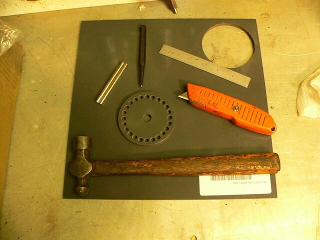
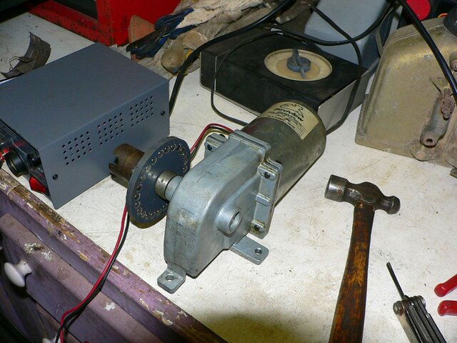
I have fabricated a magnet wheel for a Birdview H-H mount and have been using my G-Box V3000 to power the motor and detect the pulses off the reed sensor.

After a several tests I got the "E--2" error message on the display, figured I had a problem with my sensor circuit....checked, no problem...then thought the sensor itself may be bad but didn't know how to test it, and I didn't have another handy to switch it out. The motor wouldn't even move slightly, like it would if it had an issue with the sensor circuit.

Tried to "Reset" via the remote (several times) to clear the memory and also unhooked it from the power, no help.

Then decided to hook it up to another BV mount (with the 1.2 Prodelin on it) that I have been using it on.....nothing, still get the E--2 error display.

Looked in the User Manual and didn't see anything, then went to the Sadoun website and found this:

"E2 Message on Display:There is only one error message -- E2 message for GBox. E-2 Message means NO PUSLES detected.

Possible causes:


  • [*]Re-check the wiring connection from the actuator to the GBox
    [*]Make sure the actuator is not stopped due to Mechanical Limit.
    [*]Check if the Reed Switch Sensor in the actuator is broken.
    [*]Check if the Motor is broken.
    [*]The Fuse inside the GBox might be broken."


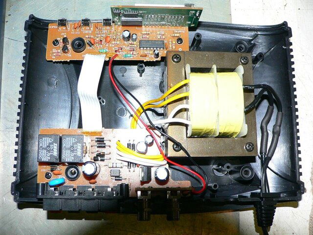
I believe I'd verified the first 4 of the items in that list so I opened the case up to look for the fuse. I'm definitely not an components-level electronics repair guy, but I don't see anything that is obviously a fuse. If it doesn't look like an old or new style automotive-type fuse I probably wouldn't recognize it anyway, that is what I was looking for.

Has anyone replaced a fuse on a G-Box, or can you give me any direction on this? :confused:

here's pics of the G-Box guts and a couple of my magnet wheel caper, to boot. :D
 

Attachments

  • Sat BV Magnet Wheel Fab.JPG
    Sat BV Magnet Wheel Fab.JPG
    161.7 KB · Views: 315
  • Sat BV Magnet Wheel on Motor.JPG
    Sat BV Magnet Wheel on Motor.JPG
    200.6 KB · Views: 311
Both Directions?
Do you hear the GBox trying to move the Dish?

Yep, tried both directions and No, it's not (audibly) even trying to power the motor. :(

edit: When you press the button to call for the G-Box to move the motor you can hear a slight click in the G-Box (which I believe is normal) but the motor is not receiveing power/moving any whatsoever.
 
Last edited:
and for my next trick I will remember to attach the G-Box pic: :p

gotta get for now, back later, thanks.
 

Attachments

  • Sat G-Box Guts.JPG
    Sat G-Box Guts.JPG
    247.1 KB · Views: 395
@phlatwound,

I have a G-box open (a near lightning strike took it out),
and I can't see a fuse in it either.

I have another G-box 3000, and once in a while it also displays "E-2".
But, I keep trying to move the dish (it does move a little, I can hear the
actuator) and eventually it will start to work correctly.
But, of course, none of the settings/positions are right ;-( because
it was moving.
 
Try moving a magnet passed the sensor, see if the counts go up or down.

thanks Lak, I will try that tomorrow, it will be easy to do since this rig is still on the bench and the sensor is not permanently attached, I can just move it past my magnet wheel.

@phlatwound,

I have a G-box open (a near lightning strike took it out),
and I can't see a fuse in it either.

I have another G-box 3000, and once in a while it also displays "E-2".
But, I keep trying to move the dish (it does move a little, I can hear the
actuator) and eventually it will start to work correctly.
But, of course, none of the settings/positions are right ;-( because
it was moving.

thanks trinity13, I figured someone had opened one of these units up and took a look inside.

From the description I think there must be some kind of fuse or circuit breaker, I just don't know what I'm looking for I guess. :confused:
 
I rather doubt you'll find a fuse or breaker just for the motor power. It may be current limited instead. If you put a voltmeter on the motor terminals on the back, does it register any blip going either direction? You should see something quick even if the error indication comes up immediately. Without any voltage to the motor, you should check the +36V supply; try the diodes on the PCB for the rear panel. It looks like there are two supply voltages, one for the motor and one for the logic.
 
I rather doubt you'll find a fuse or breaker just for the motor power. It may be current limited instead. If you put a voltmeter on the motor terminals on the back, does it register any blip going either direction? You should see something quick even if the error indication comes up immediately. Without any voltage to the motor, you should check the +36V supply; try the diodes on the PCB for the rear panel. It looks like there are two supply voltages, one for the motor and one for the logic.

thanks for your input, pendragon. I put my meter on the motor terminals and there is no indication of any voltage, not even a blip. I see 4 diodes (marked D1-D4) right where the transformer outputs connect to the PCB, but don't know how to test them so I didn't try that.

I did notice that when I press the "right" arrow button there is a plainly audible click (relay?), but when I pressed the "left" arrow button the click is much quieter.

Try moving a magnet passed the sensor, see if the counts go up or down.

The display does register counts when I move a magnet past my sensor. Unit powers up and down with the remote, and seems to respond to all other remote functions, just no juice to the motor.

By now it should be pretty obvious that I am pretty ignorant when it comes to troubleshooting electronics, so unless someone has some more suggestions (that can be understood and attempted by a greenhorn) I think I'll just give Sadoun Sat. a call today and see if they can help me out with this, thanks for all of your thoughts. :)
 
Phlatwound,

If there is indeed a fuse withing the box, you might try looking for a device that looks like a short, squatty cylinder. Possibly rust, brown, tan or light grey in color and generally soldered to the board or inserted into a round base attached to the board. This is a common fuse style used in such components. Another fuse style looks like a resistor, with axial leads. Look over the circuit boards for any silk screened "F1" some nomenclature that might indicate "FUSE".

As for the diodes, they can be easily tested (sometimes in the circuit) but best to unsolder one end and check them with an ohmeter. With the Ohmeter leads attached in one direction, the diode should read 600 to 800 ohms and in the other direction, it should indicate an open circuit. If you detect a direct short (zero ohms) or an open in both directions, then something is wrong with at least one of them. Measuringor checking them in the circuit may give misleading results. You might be reading some other component as well.

Since you found four diodes locally grouped, that is likely a full wave bridge rectifier (for converting AC to DC current) as part of the power supply.

RADAR
 
Phlatwound,

<lots of good info and suggestions>

RADAR

thanks Radar, I looked over the boards with my magnifier and didn't see anything that that was designated "F" or fuse. As far as soldering or unsoldering anything (that I would ever want to work again :D ), that is way beyond my skillset, my welding is bad enough!

I would check if there is voltage coming out of the Transformer.

Got about 12 VAC coming out of the Wht-Wht side and about 35 VAC coming out of the Yel-Yel side to the point where they hit the "transformer" end of the diodes.
 
If you are still Bench testing....
Can you have someone "shake" a magnet over the sensor, while you press the East or West button, with a meter connected to the Motor connections?
My though is the GBox is not "feeling" the pulse fast enough and errors.
 
If you are still Bench testing....
Can you have someone "shake" a magnet over the sensor, while you press the East or West button, with a meter connected to the Motor connections?
My though is the GBox is not "feeling" the pulse fast enough and errors.

Lak, I'll give that a try but I don't think that is what is wrong. The box was counting pulses perfectly with me holding the sensor (by hand) about 1/8" from the magnet wheel. I was getting 48 counts per revolution (24 magnets x G-box doubling).

I think even with no sensor attached the box will attempt to power the motor for an instant, and that power should show on the meter, even without a sensor attached? Of course it would show the error message as soon as it didn't get a return pulse from the sensor, but still it would power the motor first?

I know I moved stuff around some, and hooked and unhooked a time or 3 while I was playing but I didn't have any exposed leads and never saw a spark, or saw/smelt any "magic smoke" escaping. Pretty sure I was unplugged whenever I was making changes anyway.
 
The clicks you hear are the east/west relays kicking in. That's at least a positive sign. The unit will send voltage to the motor for an instant even if there are no pulses coming back from the sensor. Since you don't hear the motor budge and see no voltage with a meter on the motor terminals, this makes the +36V power supply suspect.

First make sure the transformer secondary is ok. With the unit plugged in, measure the AC volts across the yellow transformer leads. You should see something around 30-35V. Next check the rectifier circuit. Put your positive meter lead on the cathode (line side of the diode) of either D1 or D2. Put the negative meter lead on the anode (no line) of D3 or D4. You should see 40-50V DC. If these are ok, I would be looking for burned out traces or fried relay contacts.
 
....First make sure the transformer secondary is ok. With the unit plugged in, measure the AC volts across the yellow transformer leads. You should see something around 30-35V. Next check the rectifier circuit. Put your positive meter lead on the cathode (line side of the diode) of either D1 or D2. Put the negative meter lead on the anode (no line) of D3 or D4. You should see 40-50V DC. If these are ok, I would be looking for burned out traces or fried relay contacts.

I have 35V at the yellow leads and will check the rectifier circuit later today if I get a chance.

Your instructions are very clear and understood, much appreciated. :up
 
I went to check for voltage across the rectifier and found at least part of the problem, and it can be seen in the pic I posted earlier in this thread.

If you look just to the left of where the 2 yellow and 2 white wires hit the PCB that has the F-connectors and motor power/sensor lugs, that is where D1-D4 are...and D3 is popped apart.

If I knew what part to get, and if I could solder I might try to fix this, but still couldn't be sure if that is all that is wrong or what caused it in the first place. :(
 
Phlatwound,

Go down to Rat Shack and pick up four 1N4002 diodes (they should have this diode or something fairly similar). Desolder the existing four diodes on your PC board. Get some "solder wick" while you are at rat shack for the desoldering process. Use a flat soldering iron tip (about 1/16 inch wide) and suck up the old solder with the wick. You might need to apply some fresh new solder to the joint to refresh it a bit before being able to "wick" it up with the solder wick. Old solder joints may need a bit of a nudge to get the solder to flow properly.

Then install the four new diodes.

Get an old, junk circuit board to practice on first, so you become proficient before working on your good board.

The 1N4002 diode is a general purpose diode and will work very well for a bridge rectifier application like this one.

Install the new diodes in the same orientation as the old ones. Pay attention to the circular band on one end of the diode (that is like the polarity indicator of a battery and each diode has to be installed in the same orientation as the old ones).

You can do this! It is fairly easy, just do some practice runs on some old piece of junk first.

The blown diode in the bridge rectifier circuit probably just failed on its own (died of natural causes). Hopefully there are no other components that are defective. This is a very inexpensive avenue to find out (the diodes should be pennies each for cost).

[ame="http://en.wikipedia.org/wiki/Diode_bridge"]Diode bridge - Wikipedia, the free encyclopedia@@AMEPARAM@@/wiki/File:Bridge_rectifiers.jpg" class="image"><img alt="" src="http://upload.wikimedia.org/wikipedia/commons/thumb/e/e8/Bridge_rectifiers.jpg/220px-Bridge_rectifiers.jpg"@@AMEPARAM@@commons/thumb/e/e8/Bridge_rectifiers.jpg/220px-Bridge_rectifiers.jpg[/ame]

RADAR
 
Last edited:
if your camera has macro you can take a closer shot of the problem . i think i did locate the problem mentioned above .

Just a question for those whoe are good at soldering. since the problem seems to be with one diode couldn't you just solder "bridge" ( not to be confused with the bridge rectifier above) that one diode? (without removing the problem diode)
 
Status
Please reply by conversation.

Users Who Are Viewing This Thread (Total: 0, Members: 0, Guests: 0)

Who Read This Thread (Total Members: 1)