Ok y'all. Linuxman and I had a little conversation yesterday afternoon, and we both decided I'd need to post some pics of what I have. We had a lightening storm about a month ago and my dish stopped counting.
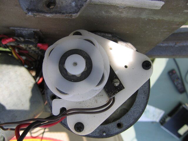
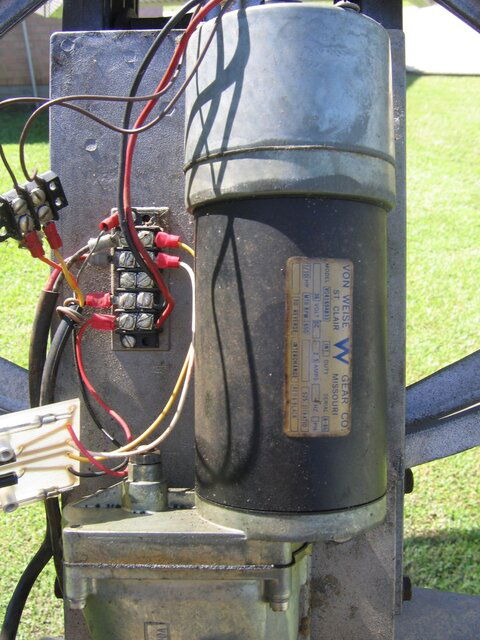
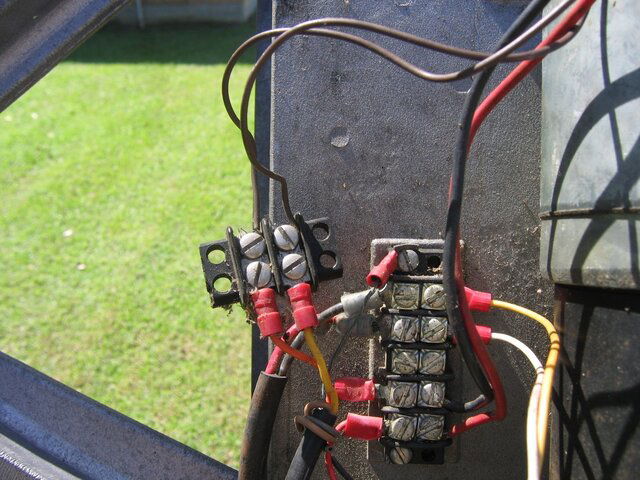
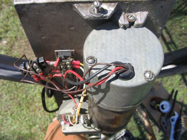
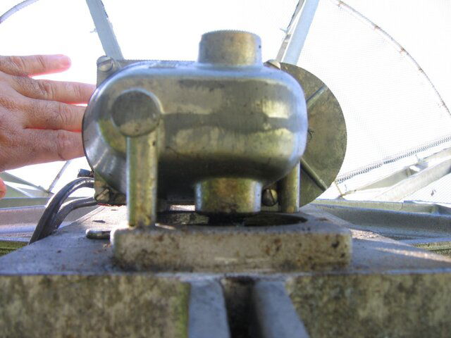
I took the cover off and had a look. looks like the wires go to the top side of the motor, underneath the silver colored cover. Problem is, I cannot figure out how to get that cover off without removing the motor. And it looks like the motor and the gearbox do separate ( see photo from the bottom, four screws), But if I do that the dish is gonna flop over, so I guess I would need to run the dish down and support it somehow. Sound okay so far?
Take a look at the pics and tell me what ya think, y'all!
(OH, big pics for you, Anole. Put your glasses on)
")

")