Sending the ASC1 into retirement?AJAK

Status
Please reply by conversation.
Well, a quick update...

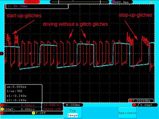
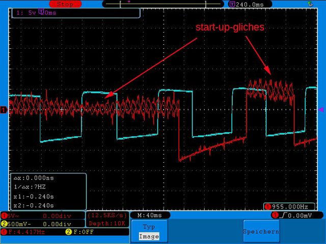
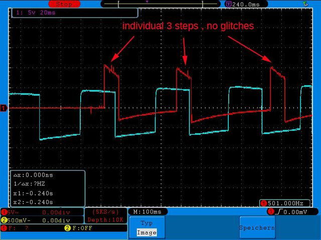
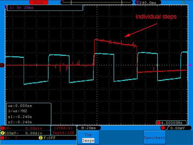
Magic Static went over to Pdiddy's place today to apply Ponny's fix and the 3 capacitor fix on the motor feed. His USB/Serial converter had no love on Pdiddy's computer, so he left his personal ASC1 with 20140702v1 firmware version already installed and another simple suggestion that I had made to twist the M1/M2 leads connecting the rear panel strip to Con102 on the PCB and run the twisted pair perpendicular to the other wires.

Initial testing shows no positioning errors, but they will have Pdiddy exercise it hard for a few weeks before the thumbs-up/down. Which mod, firmware, filter or combination made the difference and has it fixed the issues... remains to be determined. :D
 
Hello,

who wants to test a Smittriger for the ASC to 1 meter. In the annex of the schematic. The design has been tested.

Ponny
 

Attachments

  • smittriger ASC1.pdf
    20.1 KB · Views: 106
Hello,

who wants to test a Smittriger for the ASC to 1 meter. In the annex of the schematic. The design has been tested.

Ponny
 

Attachments

  • smittriger ASC1.pdf
    20.1 KB · Views: 199
  • Like
Reactions: Magic Static
Yep best I can figure(was doing a little reading) this has been replaced with the 4000B series. So 4093B or similar. For sure though do your on research before you order one. I don't have time right now to read to deep into it and study the circuit.
 
  • Like
Reactions: Magic Static
Hello,

I have done many tests with the counter of the ASC 1. With the Schmitt trigger or Reed Relays. The pulses are clean without interference at the counting input. After about 3 to 4 times driving a Satposition, he has too much counted up to 10 pulses. Here, a software or hardware error exists in the device. In the photo you see the clean signal without any errors.

Ponny
 

Attachments

  • Impulse.jpg
    Impulse.jpg
    73.1 KB · Views: 145
  • Like
Reactions: Magic Static
I use a cycle counter to measure point A to point B movement of 250 counts. Record the count, clear the counter, return B to A and record the count. Repeat.... I perform this test with 100 repetitions without count error.

What is the difference in the system testing that we have perfect counts with 100+ point A to point B passes, but you are having 10 count error after 3 or 4 repetitions? Is the count error always short or long for landing on the programmed position?
 
To drive a Ajak with Usals I replaced the reed-switch for a pulswheel with 48 slots (necessary to provide 40 pulses / degree polaraxis rotation) and a slotted optical IR switch .
I wonder , could such pulser be the solution for the problem with Ajak ?48 pulswheel.jpgPulser housing inside.jpgPulser housing.jpgpulser comp.side (2).jpg
 
To drive a Ajak with Usals I replaced the reed-switch for a pulswheel with 48 slots (necessary to provide 40 pulses / degree polaraxis rotation) and a slotted optical IR switch .
I wonder , could such pulser be the solution for the problem with Ajak ?View attachment 100320View attachment 100321View attachment 100322View attachment 100323
Very nice modification!:clapping Can you provide any detailed info on the parts you used for this mod, schematic for pulse circuit, etc?:)
 
Hi,

after many tests I was investigating probably the cause of the incorrect counting of pulses. Look at these pictures in the annex you the oscilloscope. During the starting and stopping of the motor voltage is regulated. In the the interference caused the period of the scheme. The single step, the voltage is not regulated, but is maximum. These counts are without errors. You can see this on the screen step. You would have to test a software in which this rule does not exist. The V-box II or G-box also controls not the voltage at the start or stop. Still not counting errors occur.

Ponny
 

Attachments

  • start_sstop1.jpg
    start_sstop1.jpg
    102.5 KB · Views: 169
  • start.jpg
    start.jpg
    89.2 KB · Views: 145
  • stop.jpg
    stop.jpg
    89.4 KB · Views: 145
  • steps.jpg
    steps.jpg
    82.4 KB · Views: 143
  • steps1.jpg
    steps1.jpg
    79.2 KB · Views: 143
  • dauer.jpg
    dauer.jpg
    85.2 KB · Views: 169
  • start_stop2.jpg
    start_stop2.jpg
    101.8 KB · Views: 136
I have been communicating with Ponny about this matter and he had provided this data earlier on the week. For those that don't know, Ponny is a Titanium Satellite reseller in Germany. We are providing him test firmware next week with no ramping (power regulation). Since the issues cannot be replicated on our equipment, Ponny has been testing various firmware with his system. He is passing this information to update other members with our emails.

The firmware since 20140401v1 received sensor counts after motor voltage termination for a few seconds and works with our bench motors and Ponny's low current draw motors. Ponny pointed out in an email that this voltage regulation testing was noted on high current draw motors, but not with low current draw units. The highest current draw motor on my bench is 2.5 amps and Ponny is testing with 4 amp draw. This could be the difference in our bench testing.
 
Status
Please reply by conversation.

Users Who Are Viewing This Thread (Total: 0, Members: 0, Guests: 0)

Who Read This Thread (Total Members: 1)