Sending the ASC1 into retirement?AJAK

Status
Please reply by conversation.
I started the AJAK sensor mod in this thread http://www.satelliteguys.us/xen/threads/10-cm-perf-on-ajak-h180.311276/
The design of the current revision is based on the original design. All magnets polarized the same way N or S and a reed switch that is placed so it counts each passing magnet twice. The stock sensor was 5 magnets for 10 counts per revolution. I use 10 magnets for 20 counts. The wheel pictured below.
SensorRev2 012.JPG SensorRev2 013.JPG
There are two switch and cover plate assemblies that I am working with. One uses a molded body reed switch and the other is a glass tube like the original.
SensorRev2 011.JPG SensorRev2 010.JPG

SensorVer3 010.JPG SensorVer3 013.JPG

After rewiring the AJAK with ribbon cable it looked like this.
Pinnacle refit 019.JPG Pinnacle refit 025.JPG
Because the sensor wiring is so close to the motor can it didn't work with any controller at this point.
I moved the wiring in the terminal block to move the sensor wiring away from the motor. It helped but wasn't perfect.
TBlock 014.JPG

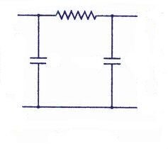
I decided to try and remove as much of the sensor wiring as possible to further remove it from influences from the motor. I also added a capacitor to eliminate switch bounce type signals. But the latest firmware had already saw to that issue.
Again 017.JPG Again 021.JPG Again 028.JPG Again 030.JPG andagain 002.JPG
This is where I am at today. The VBox likes this and the ASC1 doesn't :(
I would really like to know if it worked with a stock sensor, but I don't have one.
 
You are overdoing it with all those counts per revolution. Slicing up 1deg into dozens of counts is unnecessary when the accuracy of the dish beam width is much wider at +/- 2 deg. Loose the double count and drop down to 2 magnets and your AJAX will work fine.
 
You are overdoing it with all those counts per revolution. Slicing up 1deg into dozens of counts is unnecessary when the accuracy of the dish beam width is much wider at +/- 2 deg. Loose the double count and drop down to 2 magnets and your AJAX will work fine.
That might work for your purposes, but not mine. The AJAK does work fine, just have to use a VBox.
 
That might work for your purposes, but not mine. The AJAK does work fine, just have to use a VBox.

Magic,

It's not for my purposes, I'm just trying to bring light to the overstated subject often found in these forums about excessive attention toward high actuator count. I'm trying to discourage members into high count mods to any dish mover as it will get you no improvement in dish positioning. The original engineering is well within the beam width of any dish.
 
Well having used the high resolution sensor in direct comparison with a sensor of half that resolution(stock count), I find it to be better at tuning the weaker Ku transponders. There are no channels I can't get with that 10' dish, even being on the edge of the footprint. The stock sensor was in 10th of a degree increments, which I wouldn't call excessive at all. On Ku it was one click and you lose lock if you had it. I double the count and it's great. But anymore, I agree is pointless. I did do a 16 count wheel, but the doubling switch technique enabled me to easily make 20 counts. The math is easier with 20 too. I guess I'm just not a hexadecimal type ;)
 
You should see what I did to a Venture sensor. From a stock 32 counts per inch to 96 counts LOL But what is really amazing is how well the ASC1 handles that setup compared to the other three DiSEqC boxes I have. It flat blows the competition away. It's fun to watch :)
 
your original thread was a fantastic read, excellent design and engineering.
my only theories (at this point) would be
1. the asc1 has a much stronger power supply, is it moving the magnet wheel too fast?
maybe not constantly, but maybe it occasionally skips a count or two?
2. i know the asc1 has software anti-switch-bounce but i would still try a hardware de-bounce circuit (not just a capacitor)
 
  • Like
Reactions: Magic Static
Should be able to tack this someplace inside the ASC1. It's surface mount, so you'd need a little 'hobby' board to mount and wire it in. Maxim makes some cool stuff.

http://www.maximintegrated.com/en/p...tage-monitors-sequencers/MAX6816.html/tb_tab0

Looks like the chip puts out a logic level pulse. May not be high enough if the ASC1 is expecting 12V pulses. Could add a simple voltage converter to increase the pulse amplitude to 12v or higher..
Like this one: http://www.mouser.com/ProductDetail/STMicroelectronics/ULN2803A/?qs=FOlmdCx%2bAA1lVc/YEXA4pg==


Mouser has no minimum purchase requirement. Good outfit.

http://www.mouser.com/ProductDetail/Maxim-Integrated/MAX6816EUS T/?qs=sGAEpiMZZMunEhqKs81nFFSrWToUXdqM1yTYHzBQirc=
 
Last edited:
In reviewing Magic Static's scope captures there was no apparent switch bounce. There is a high noise threshold and RF spikes occurring within the closed portion of the cycle. In his case, I don't believe that switch bounce plays a role in the count errors.

Magic Static's wheel resolutions are well within the specifications of the ASC1. I believe at the fastest point of movement, one wheel type operated at 24 or 30hz and others at a lower rates. Doubt that motor speed plays a role as the ASC1 reliably handles cycles up to 50hz.

Voltage drop on the sensor is not likely an issue as the ASC1 only requires microvolts on the return in order to trigger. In my opinion amplifying the voltage would have negative influence on the circuits signal to noise ration and just introduce yet another variable.

His original switch project that we dealt used normally closed switches. The open to close ratio was the opposite of typical sensors, which use normally open switches. Once he swapped to a normally open switch, many of the errors were eliminated or minimized.

Magic Static, maybe you could share scope captures of your current switch project so we can see the current cycle rates and noise levels? Maybe comparison with a G/V box in operation? Maybe other members might have observations on something that we have missed.

Too bad we couldn't get you an original AJAK sensor for comparison with your custom switch projects! This would help address some of the variables that appear in your testing.
 
In reviewing Magic Static's scope captures there was no apparent switch bounce. There is a high noise threshold and RF spikes occurring within the closed portion of the cycle. In his case, I don't believe that switch bounce plays a role in the count errors.

so it seems that the rf spikes from the sensor are causing extra counts? (i wish i could see the scope pix)
so smoothing the pulse out of the sensor to a nice smooth logic pulse would probably eliminate the problem?

Voltage drop on the sensor is not likely an issue as the ASC1 only requires microvolts on the return in order to trigger. In my opinion amplifying the voltage would have negative influence on the circuits signal to noise ration and just introduce yet another variable.

i agree, what about doing the opposite and weakening the pulse?
maybe as simple as putting a (random guess) 4.7k resistor in series with the sensor)
i would even take it just a little further and use an r-c low pass filter (see attached)
also, if that don't work, i bet an ldr compressor would.
i really like the fact that the asc1 is very sensitive to pulses, it seems it would be easier than other controllers for using other kinds of sensors other than magnetic.
definitely on my list of things to buy!!

His original switch project that we dealt used normally closed switches. The open to close ratio was the opposite of typical sensors, which use normally open switches. Once he swapped to a normally open switch, many of the errors were eliminated or minimized.

maybe it would work better if the pulses were inverted?http://www.electronics-tutorials.ws/logic/logic_4.html

ya, i think the general issue here is that any time that you do something non-standard it will have wrinkles that will need to be ironed out (if your luck is like mine, lol)
i think the op was giving up far to quickly after his non-standard setup didn't work without ironing out the wrinkles.
maybe just a bit of short term frustration?
anyway, i'm sure we can get it figured out.
i bet eliminating the rf-noise is the key, and i would probably start with the r-c low pass filter.
 

Attachments

  • r-c.jpeg
    r-c.jpeg
    4.2 KB · Views: 96
  • Like
Reactions: Titanium
Thanks Magic Static for posting the screen shots! Do you remember what the open and closed duration mS were on the normally closed switch?

Ynnedibanez, once the circuit is opened or closed, the ASC1 only reads as a single pulse until the voltage is cycled.
They only issue that I noted with the normally closed switch was the short ratio for the open duration.

Some interesting suggestions that I would like to experiment on an AJAK when an owner wants to play. :D
 
The normally closed switch version of the 20 count sensor I used two switches in series. I achieved a 40% on time.

So I think the problem is motor noise, So I "googled it" Some interesting read
Filtering Motor Noise
Below are three simple ways that capacitors can be added to a motor in order to reduce any noise that motor may be producing.
edit] Single Capacitor Filtering[/paste:font]

Figure 1. A simple one-capacitor noise filter

The simplest filter involves adding a capacitor across the motor terminals as shown in figure 1.
Since a capacitor will conduct only currents that are changing at a high frequency, a single capacitor (typically 0.1µF) wired across the motor terminals (as shown in Figure 1) will act as a short circuit for high-frequency electrical noise, while not affecting the DC current to the motor at all. This reduces conduction of noise along the motor wiring.

Also see: Ben Hitchcock's tutorial Isolating Motors
edit] Two Capacitor Filtering[/paste:font]

Figure 2. a simple two-capacitor noise filter

Sometimes a motor is particularly noisy. In this case it may be necessary to use two-capacitors to reduce the motor noise. As shown in Figure 2, one side of each capacitor (0.047µF usually works well) is soldered to one of the motor terminals, and other side is soldered to the motor’s case.

This configuration makes the motor's case act as a shield, thus also reducing radiated noise. This makes it more effective than the one-capacitor technique described above.
edit] Three Capacitor Filtering[/paste:font]

Figure 3 - A simple three-capacitor motor noise filter

The one- and two-capacitor filters can be used in combination making a three-capacitor filter. As shown in figure 3, one capacitor (again 0.1µF) is connected across the motor terminals, and one capacitor (0.047µF) is connected to each of motor terminals and the motor casing.

This last configuration is the most effective, and will all but guarantee that motor noise will not be the source any odd circuit behavior you may run into.

Note there is absolutly no 'guarantee' that this configuration will eliminate electrical motor noise.


Do you think this will work?
 
  • Like
Reactions: KE4EST and Titanium
I was ready to give this project a rest for a while. Some other things I want to do. But you guys have dragged me back into thinking about this again. Now I've learned some new things and I have to try it :). It could be as simple as twisting the power wires to the motor from the limit switches. But I'm going to start by pulling the armature out of that motor and refinish the commutator. I will also move the capacitor to the motor itself. I will summon all my powers and spells and vanquish this foe "Motor Noise"
 
Looking forward to hearing about and "seeing" your results..aka I wanna see some scope shots after each mod, if you take some that is.
 
Well one of the other things I wanted to do decided it was time this morning. I came across a 9' BirdView Perf. The reflector is badly bent and not Ku suitable sized perforations :( But the mount and motor are intact. I was surprised to find this one had already been converted from the potentiometer to a magnet wheel and reed switch. The "wire twisting: method of noise control was employed in this installation.
 
  • Like
Reactions: Titanium
I never have seen figures 2 or 3 on a satellite system, but it makes a ton of sense to take the stray RF noise to chassis! I do recall twisting the motor and mechanical stop wires for noise suppression. Keep us in the loop.
 
...I came across a 9' BirdView Perf...

I have never seen a 9' BV perf. Saw a pic of someone holding a tape on a 9'-6 BV solid. Every BV I have seen with my own eyes, or laid hands on, was 8'-6 (solid or perf).

Did you measure the reflector? If it is actually 9'-0 it is a rare "Bird" indeed.
 
I have never seen a 9' BV perf. Saw a pic of someone holding a tape on a 9'-6 BV solid. Every BV I have seen with my own eyes, or laid hands on, was 8'-6 (solid or perf).

Did you measure the reflector? If it is actually 9'-0 it is a rare "Bird" indeed.
You are probably right. It was face down in the dirt and I measured roughly across the back. I was sure it was more than 8'. It is a Model # AP2028
 
Status
Please reply by conversation.