The Birdview Vs. Radio station RF....AGAIN! Ideas?

  • WELCOME TO THE NEW SERVER!

    If you are seeing this you are on our new server WELCOME HOME!

    While the new server is online Scott is still working on the backend including the cachine. But the site is usable while the work is being completes!

    Thank you for your patience and again WELCOME HOME!

    CLICK THE X IN THE TOP RIGHT CORNER OF THE BOX TO DISMISS THIS MESSAGE
Status
Please reply by conversation.

radio

"On the Air" in MI
Original poster
Pub Member / Supporter
Oct 13, 2007
3,725
1,003
West Central Michigan
(Insert soap opera music here) .....When last we left our happy birdview owner at a West Michigan radio station, he was using a V-box 7 and a simple low-voltage relay circuit with a rotary encoder at the dish's gear to properly position the dish, and it worked well.......until......(insert dramatic music here.)

About three nights ago, swinging the dish back and forth between the feed of the Tiger game and other programming, the positioning just quit working. To induce enough pulses on the V-box, we had a mechanical relay circuit driven from a wall wart and a rotary encoder. We've tried new plug in relays in case one was bad. We've changed the power supply to the relay, (we were running 12 volts so it would get enough "oomph" to run, tried actual voltage rating of 5.0 and it didn't make it work, either.)

Then, a solid state circuit was designed, which took the input voltage, and supplied exactly what the rotary encoder needs to provide the pulses to the V-box. What we found was, the RF from the radio station is enough to light even a high-current LED incorporated into the circuit. The first rotary encoder failed over time because we had to run it at a higher voltage (12 volts) than it was rated for it to function. Our engineer believes it was because of the RF on the line from our transmitter, which was enough to light a high-power LED before the ground wire was connected!

Somehow, even with the new circuit, 5 volts in the V-box is about 3, give or take at the dish. 12 at the V-box was less than 12 at the dish. We've changed wiring in case there's a fault there, with the same results, and we even used twisted pairs of wire to deliver signal and voltage. The new circuit goes through one more test today with some extra "bleed-off" for ground as recommended by our transmitter engineer, and we hope it works. But, in talking about this with another engineer, he suggested we go back to the following:

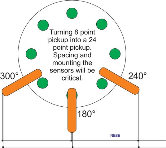
Since the only reason the V-box won't work on the birdview is not enough pulses, couldn't we increase the AMOUNT of reed switches that trigger, and carefully place them in the circle's arc so each magnet triggers 3 times as the attached diagram suggests? It would not induce RF, and would be simpler than all the circuits, require no extra power other than what's already on a V-box line, and maybe it would give us 24 counts per revolution, given that (8) is what we had to start with on the old wheel! The counts would have to be carefully offset as shown NOT to trip at the same time, however.

(music stab here) Tune in next time when we hear......."The V-box is working...the V-box is working".............we hope!
 

Attachments

  • satellite wheel-3 reed switches inline.jpg
    satellite wheel-3 reed switches inline.jpg
    59.5 KB · Views: 168
I would first try a cap and choke tuned to your RF carrier freq. (Low Q) The choke would be placed at the pulse lead at your encoder. The cap, at the junction of the choke and lead, to ground. If this is within shielded cable, "satellite ribbon cable" or equivalent, ONLY ground the shield at the dish. Do not use the shield for carrying signal or power.
V-Box---cap to gnd--choke----encoder
Or at the V-Vox end of the wire: encoder---cap to gnd---choke--V-Box
One or the other should work, IF the RF that's causing your interference is being picked up by the wire, and not being directly induced into the encoder.
To get 5 volts at your encoder, place the voltage regulator at the encoder. Feed the wire, that feeds the regulator, 12v. A 7812 regulator with caps and wires can be weatherproofed by potting them in epoxy.
 
Thanks for the heads-up and the tip! Our engineer had similar thoughts, and I've forwarded this to him. Ah, the joys of living under 5kw, plus an FM! We'll "keep you posted" so, "stay tuned!"...and thanks again!
 
I'll second FaT Air on this as I used to be chief engineer for several broadcast stations. All of what you describe can be fixed by proper shielding, bypassing and grounding. How this is done will depend a bit on the RF involved, but none of it is magic.
 
And, thank YOU, too, Pendragon! RF is a funny beast as you know, and unique to us broadcasters, not the average "Joe America" trying to install their stuff at home. Was shocked that our changeover to solid state would be affected as much as it was, but should have updates early this week! Can't wait to get the Birdview moving again! I miss it!
 
also ferrite beads at the right places may help, as well as changing the length of the control line. check for wave length and harmonics.... I have forgotten most of what I ever learned about that, including how to test (but I do remember using a short florescent tube to locate peaks).
 
Small Ferrites won't have enough Z at am band freqs, but they would help if that FM is also a culprit. I forgot about lead length and resonance. Another angle to attack.
 
Just a suggestion: Fiber optic cable between the dish & the station. Reed switch(es) controlling the emitter at the dish & a 5V logic detector at the V-Box.

Or use a slotted wheel with a unit such as this to drive the emitter at the dish:hxxp://www.alliedelec.com/search/productdetail.aspx?SKU=3870943
 

Attachments

  • PhotologicSlottedOpticalSw.pdf
    194.3 KB · Views: 172
Last edited:
With all the RF your getting Jim, its no wonder why people say you have a glowing personality. :D

Why, thank you, kind sir! Maybe that's why the RV I live in looks more like a UFO these days! (or is that caused by 4 satellite dishes outside the RV all wired in
to the coach....hmmmm)
 
Birdview positioner held hostage, day number...hmmm..7????

With the near 4 volts average in the air and along the lines to the dish positioner from our AM signal, we've determined that the counting mechanism never sees "zero" volts, which should be switching around 5-0-5-0, etc on and off. Going to try to get same ground potential to the BV dish/mount and trailer to which all the wires connect. Going to put the rotary encoder in a metal box, and, since the cables have to cross part of the parking lot and cannot be buried, we'll put 'em in copper piping bonded electrically to both the trailer body (in which I live) along with ground, and the dish. That's next. I miss moving my BV. Almost ready to go back to the manual BV digital rotor box and the rotary pot. Wouldn't be so bad, just one more step in the procedure. (If I can even find one of those boxes anymore!!)

Still don't know if the surface mount capacitor in the rotary encoder failed due to RF, (we assume this is what quit in the first one) or whether it was the fact we had to use 12 volts on the line going "out" to the dish to get 5 back at the V-box for it to run. Could be a combination of both. Wish us luck! Even the station engineer is surprised at this issue. Might even go back to the Stegmann heavy duty encoder with only 20 pulses per revolution. It has less "resolution" but when we first used it, it worked! (couldn't fine-tune the dish as well, but as of now, I prefer that to using a 12 volt jump box to move the dish!!)
 
It's very clear there is a serious lack of understanding going on here. Until you step back and get your arms around the problem(s), you will just be shooting in the dark and not likely to hit anything.

1. From what you've described, I expect your RF field is wreaking havoc with your measurement instrumentation. These are likely high input impedance devices, probably unshielded, and not designed to give accurate voltage measurements in the presence of high electrical fields. . I would not use these for troubleshooting. Unless you know what you're doing, you're very likely being taken for a fantasy ride

2. You need to get a reliable voltage supply to the encoder and the interface circuit. This HAS to be +5V. If you're going to use +12V, the encoder and interface circuit will fail. As has been pointed out before, send a higher voltage to the encoder/circuit and use a voltage regulator to provide +5V at the dish. As the current draw is probably less than 100 ma, you can easily insert chokes and capacitor shunts at both ends of the cable to ensure the RF doesn't bleed into either the power supply or the regulator. Extra heavy bypassing at the regulator, the encoder and every chip in the interface circuit is essential.

3. The interface circuit, regulator and ideally the encoder should be in a fully shielded and well grounded box.

4. Even with a rotary encoder you likely are only passing a few hundred Hz for the VBOX counting. Your AM RF is on the order of a MHz. This means you can also heavily filter (choke and capacitor) the output signal at the shielded box and where it enters the VBOX without killing your counting pulses. You will need to calculate values to make sure.

5. It's possible the VBOX pulse sensing circuit has too high an output impedance. If so use a very low impedance driver/buffer at the dish and translate this at the VBOX.

6. The VBOX may itself be prone to RF fields. If so you may have to improve its internal bypassing.

Remember, DC isn't going to shift up and down on the length of cable you're talking about. There is no "4V" in the air. That's poppycock. There is a strong electrical field and a high impedance meter may show you a relatively meaningless potential difference. You can light fluorescent bulbs and LEDs with it - that's merely a standard party trick. However RF will get superimposed on the cable and there are plenty of ways for this to get rectified into DC if you let the RF into a VBOX or your interface circuit. If you can keep the RF out of both, your problems will likely disappear.
 
Status
Please reply by conversation.

Users Who Are Viewing This Thread (Total: 0, Members: 0, Guests: 0)

Who Read This Thread (Total Members: 1)