New user - old Birdview

I
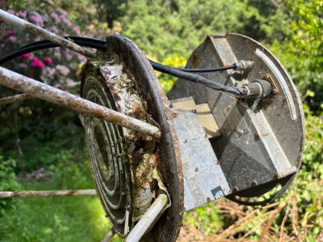
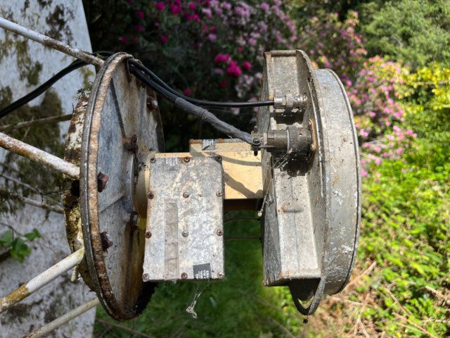
Removing the feed horn cover is very simple. Merely remove the center screw and pull it off…. Not. 45 years of entropy has left it very comfortable where it is. Should I spray it with something?

This is a lot more fun than the stuff I should be doing,
In the apparently unlikely case someone finds this when googling how to remove the cover - I sprayed it with wd-40, let it sit for a few hours and then hammered the tip of a thin flat screwdriver into the gap and twisted. The gap opened up a little so I went around the circumference inserting and twisting the screwdriver until the gap was about an eighth inch all around. Then I could pull the cover off by hand.

I had previously tried hitting it with a rubber hammer; this was ineffective and dented the cover. IMG_0370.jpegIMG_0369.jpeg
 
Your dish has great potential, but will require some modifications to accomodate changes in technology and usage since it was manufactured 40+ years ago.

As I suspected, this is an original Birdview LNA type feed. This type of feed is no longer in use and unsupported by receivers in use today. I would remove the feed hardware and only reuse the scalar. Clean and renew the scalar then hone the opening to accept a new larger LNBF throat diameter.

The Birdview FD (Focal Diameter ratio) is .39, but hobbyist, who have modded Birdview's in the past have reported success and good signal readings using current design feedhorns and modded Birdview scalar w/modded support legs to set correct FD and FL (Focal Length). Some hobbyists have addressed tbis FD and FL mismatch by fabricating new longer feed support legs, but this is a significant endeavor.

You will find several threads on this site and over on Rick's posted in the early 2000's on Birdview feed modificstions. Past threads also discuss the mount modifications for declination setting.
 
Oh well, I'm sorry to hear that but not surprised. Which is the scalar? Is it the aluminum structure with the fins, (presumably a wave guide)? I have access to CNC plasma tables and industrial 3d printers. Could I conceivably fabricate something that would work? Is it simply a matter of placing the new modern LNBF in the correct position?

Thanks again for your help and advice, all of you who responded. I see I have a great deal to learn and it's not going to be as simple as I'd hoped.

There's this, lots of info: Pendragon vs. the Birdview

IMO, Ricks got the most info on Birdviews: https://rickcaylor.websitetoolbox.c...owas=threads&btnSearch=Search&action=doSearch
 
  • Like
Reactions: norman881
Is it ok if I continue this thread here? I may get a bit off topic occasionally. I don't want to annoy anyone or waste their time but I might want to post about my progress, thoughts and experiences.
Yes, I encourage you to leave it all in this thread here! I put those links there for you to read, to maybe figure out some things you need to do. There's good stuff from people that already did it.
 
bombu,

I have a motorized 8.5' BirdView. It's my second one.

Am currently using it for KU band. I made a circular holder for a KU LNBF out of 1/2" expanded PVC (See photo). I also made a circular LNBF plate with two holes for dual KU / C-Band operation, but am not currently using it.

Mine came without feed support rods, so I had to make those out of threaded rods from the hardware store.

I would be happy to provide any construction details if you would like.

Brett

BVFeed.jpg
 
Great, thank you.

Titanium, is the .39 f/d ratio you cited from manufacturer's specifications or is it empirically determined? I stretched strings across and came up with 19 inches depth for a f/d ratios of .375. Google's Gemini ai chatbot suggested a f/d ratio of .38 (for an early '80s 9.5' solid Birdview) which implies a depth of 18.75 inches. The exact diameter is also a bit fuzzy since the edges are rolled. Also, getting my strings exactly over the center of the dish is problematic.

It seems to me that measuring the signal strength and adjusting the LNBF to maximize the signal would be the only reliable method.
 
I

In the apparently unlikely case someone finds this when googling how to remove the cover - I sprayed it with wd-40, let it sit for a few hours and then hammered the tip of a thin flat screwdriver into the gap and twisted. The gap opened up a little so I went around the circumference inserting and twisting the screwdriver until the gap was about an eighth inch all around. Then I could pull the cover off by hand.

I had previously tried hitting it with a rubber hammer; this was ineffective and dented the cover.View attachment 181615View attachment 181617
Haven't seen one like that. That's a whole can of worms going on there.

The scalar is the plate with concentric rings (aka "scalar rings"). I remember way back an explanation for how they work, like they're bouncing signal back into the dish to be better focused on the center/waveguide. The waveguide is the round tube at center of scalar rings. The rectangular fittings for LNBs can also be referred to as waveguides. Basically it's anything that conducts the signal in air.
 
bombu,

I have a motorized 8.5' BirdView. It's my second one.

Am currently using it for KU band. I made a circular holder for a KU LNBF out of 1/2" expanded PVC (See photo). I also made a circular LNBF plate with two holes for dual KU / C-Band operation, but am not currently using it.

Mine came without feed support rods, so I had to make those out of threaded rods from the hardware store.

I would be happy to provide any construction details if you would like.

Brett

View attachment 181667
Brett,
Do you not have a scalar?
 
The pic may look like no scalar rings, but Ku-only feeds (and waveguides) are much smaller than C-band or C-Ku feeds. So there's likely a mini scalar there.
 
  • Like
Reactions: N6BY
If I drill/hone/ream the existing scalar to accommodate a modern lnbf, and aim the dish at Galaxy 18, (a couple of degrees from my zenith), without yet concerning myself with motorized movement or precise focal length, should I be able to get some FTA tv, even if not great reception?

If I leave the scalar where it is and 3d print spacers to move the new lnbf more into focus would that be substantially worse than extending the mounting arms and moving the scalar?
 
There should be some way to mount a Ku LNBF, which should have its own scalar ring. Can the old C-band scalar be removed or is it integral with the feed support legs?
 
Without modifying the mount to add declination, KU tracking outside of the apex of the arc will be impossible. The narrow beamwidth of a 10 ft reflector on KU requires precise arc tracking. This dish pre-dates BUD owners receiving KU. My best guess would put the vintage of this dish around 1982 - 1985.

When measuring for the FD and FL calculation, do not calculate the rolled edge. Only measure the concave surface. Been many years since I worked on a Birdview, so I am referencing the FD .39 from the mod threads.

Scalars are basically mechanical chokes, optimized to reject off-axis signals and minimize side lobes. Scalar placement in the current age is even more importand than back when this dish was manufactured. Satellites used to be separated by at least 3 degrees and overlaping frequencies on adjacent satellites would use the opposite polarity. This is no longer the practice as satellites are now often 2 degrees apart. With the reduced 4000- 4200 MHz downlink band, both polarities are typically used on all satellites without alternating polarity.
 
My two cents. Get that thing cleaned up and look for any deformation of the reflector and mount. When it is cleaned up and dry.
First thing would be to soak every single fastener and pivot with penetrating oil.
Check it real good for any structural deformations.
Work on getting it up on a pole with a good view of the Southern sky.

I bet there are a ton of guys here with a c band scalar just hanging around.
Mounting one should be a breeze. Don't suss too much about super exacting focal anything measurements. Time to tweak all of that later and fabricate any mounting methods. The scalar distance from the dish has some wiggle room.
The lnbf will be tuned like a camera and lens. Focus, skew. Highly adjustable with a proper scalar.

If ku band is the only interest. Then setting it all up with a scalar and lnbf will be straight forward.
I tried it and it works on my c band dish. Sidecar ku band lnbf. Enough signal strength to get any satellite with ku content.
Works for me.
Although a proper ku lnbf setup will most probably use the entire dish diameter. My setup uses only a portion of it and reflects around 5 or so degrees from where the same satellite is aimed at with c band. I tuned the "look angle" for best performance.

Great questions and awesome response from the fellows. But we need to get 'ole Dr. Crust cleaned up and ready for a pole first.

Feed Cropped.jpg
 
  • Like
Reactions: norman881
Without modifying the mount to add declination, KU tracking outside of the apex of the arc will be impossible. The narrow beamwidth of a 10 ft reflector on KU requires precise arc tracking. This dish pre-dates BUD owners receiving KU. My best guess would put the vintage of this dish around 1982 - 1985.

When measuring for the FD and FL calculation, do not calculate the rolled edge. Only measure the concave surface. Been many years since I worked on a Birdview, so I am referencing the FD .39 from the mod threads.

Scalars are basically mechanical chokes, optimized to reject off-axis signals and minimize side lobes. Scalar placement in the current age is even more importand than back when this dish was manufactured. Satellites used to be separated by at least 3 degrees and overlaping frequencies on adjacent satellites would use the opposite polarity. This is no longer the practice as satellites are now often 2 degrees apart. With the reduced 4000- 4200 MHz downlink band, both polarities are typically used on all satellites without alternating polarity.
Arlo, I'm sure you're correct but the dish is going to have to stay where it is for now and I'll just have to live with any deformation. I have more pressing work to do in finishing my new house.

By "ready for a pole" are you referring to replacing the six struts that support the LNB?

I doubt the dish will ever be motorized enough to use the modern automated computer based control systems. When I get around to disassembling, cleaning and lubricating the jack system I expect to reuse the antique motor controller from the original installation, if I can find it.

In the meantime I'll be satisfied if I can invest a few hours and a couple hundred bucks in it and get some reception from a single satellite. For now I don't really care too much what programming I can receive; it's really just for fun and my education.

And I am definitely learning lots!

Brian,
Is "adding declination" you mentioned referring to a more sophisticated system for moving between satellites?

Do you think the original scalar is likely well matched to this dish or with the looser tolerances of the past is it likely to have room for improvement? I'll unbolt the scalar and take some more pictures.

The dish was certainly installed in the early '80s. Now that I've retired from my school job I now longer have access to a handheld 3d scanner which would have determined how well the dish matched a parabola. I could still laser cut a template to place in the dish and see how accurate the parabola is but I'd need a formula for what parabola to use.
 
  • Like
Reactions: navychop
Unless you can see some obvious damage to the reflector I would bet the parabola is the same as it came out of the factory, those things are very rigid and hold their shape.

I added some declination to one of mine by putting spacers (washers) between the back of the reflector and the mount.
 

Comments from a newbie to FTA

Top