Repair DX100 American Electrola Radio, AM FM SW?

  • WELCOME TO THE NEW SERVER!

    If you are seeing this you are on our new server WELCOME HOME!

    While the new server is online Scott is still working on the backend including the cachine. But the site is usable while the work is being completes!

    Thank you for your patience and again WELCOME HOME!

    CLICK THE X IN THE TOP RIGHT CORNER OF THE BOX TO DISMISS THIS MESSAGE

Gray Hair

SatelliteGuys Pro
Original poster
Lifetime Supporter
Jun 9, 2012
164
74
N WV
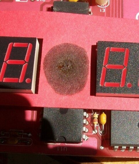
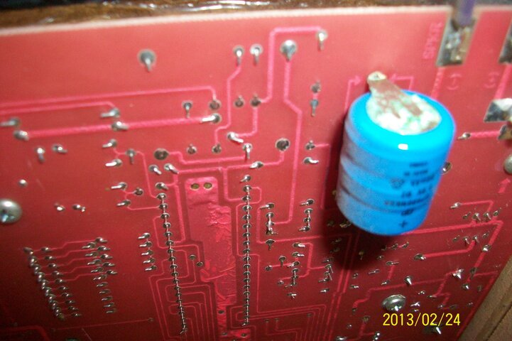
I have a DX100 American Electrola Radio, AM FM SW. It is a receiver only, which quit working many years ago. Several years ago the seller had stated that capacitors would need replaced because they go bad.

In this particular xxx://www.youtube.com/watch?v=3zUbXgNT8Oo they mentioned the backup battery being the problem.

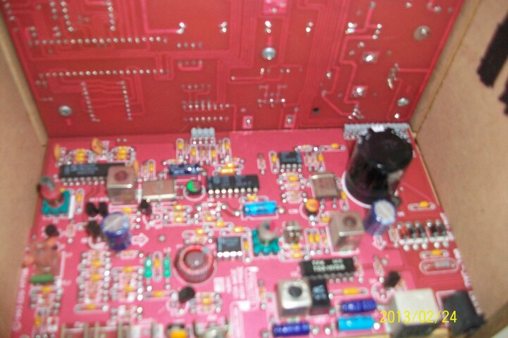
Several years back when asking about having the capacitors replaced one former repairman said send it back to the factory, well there is not any. Another response several years ago from a person who repaired circuit boards for industry said they could repair it if they had a schematic, again I do not have.

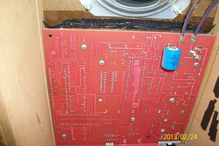
This radio was built in Pittsburgh, PA out of as many American parts as they could find. Your thoughts on getting the radio to work?
 
Well, a schematic would be nice, but it's not a deal-killer.
That backup battery isn't a challenge, but I would consider several alternatives to the original.

Electrolytic capacitors do fail.
But you wouldn't just shotgun the problem by replacing all.
There's a good chance you can locate leaking caps by visual inspection.

How about taking some well-lit, close up pictures inside the unit?

If yours doesn't power up, maybe the power supply would be the place to start! :)
And if the dog chewed the power cord, that might be the answer!
 
Anole
In looking at my notes from years ago: It is not keeping proper time. Time is going much faster than it should. The digital readout when changing stations, the last two digits does not always change at times. At other times none of the digits change when changing stations. When AM antennae is plugged in reception is poor, but when only center prong is left plugged in reception is better. (AM is a separate antennae, I am thinking ferrite type.)

I just brought it out of the attic with outside temperatures around 30 F degree’s and I do not notice the readout change situation. I will watch it when it warms up.

The radio only has two boards; I just was not satisfied with quality of pictures so there are several. I did notice corrosion around the one blue item on the board by itself.

Thanks!
 

Attachments

  • American Electrola Radio 005.jpg
    American Electrola Radio 005.jpg
    1.4 MB · Views: 415
  • American Electrola Radio 006.jpg
    American Electrola Radio 006.jpg
    986.8 KB · Views: 401
  • American Electrola Radio 004.jpg
    American Electrola Radio 004.jpg
    1,009.6 KB · Views: 442
  • American Electrola Radio 007.jpg
    American Electrola Radio 007.jpg
    982.7 KB · Views: 408
  • American Electrola Radio 011.jpg
    American Electrola Radio 011.jpg
    996.5 KB · Views: 388
Yea, the corrosion is on the big blue backup battery.
Getting an exact replacement and installing it should be trivial (if that old style is still sold)! :)
Could its failure create other problems? Not if I designed it!
I don't think so.

How is the radio powered?
Does it use an external wall wart?
If do, what voltage does it put out?
What current rating?
DC or AC?

From what I see, the radio relies on clean external power.
I take it electronics are not your thing?
Would sure be great to check the ripple (think: hum) in the supply.

Extra brownie points to ya for the YouTube vid and instant pictures!
I'm so annoyed over in FTA when people ask about things they clearly don't understand, and don't post pictures when asked multiple times!
So don't take it as criticism when I ask you to shoot again. ;)
I want to be able to read the values on the parts, and what is printed in the silk screen! :up
Sometimes there is brown residue under or at the end of a capacitor.
In some cases, that's where the pressure built up, and the cap puked its guts.
Other times it's just an adhesive used to hold the cap in place.
Very hard to tell the difference, first hand.
Almost impossible in even the best of pictures.
So that's why I'm relying on ya for really sharp shots.

Looks like the two boards plug together with two connectors.
Something I picked up from your pix.
How hard would it be to remove both to see the front of the digital board?
Do NOT take apart anything you can't get back together! Just say: no. :)
 
Looking again at the pictures, answered several questions, and generated a few more! :)

AC power comes in from a wall wart power supply.
Between the connector and front of radio, there are four black rectifiers soldered to the lower (radio) board.
That inch diameter cylinder in that corner of the board is the main filter capacitor.
Is the top totally flat or does it have any bulge to it?
Is there any discoloration where it attaches to the board?
Can you read any markings on the black capacitor?
I 'll guess: 500 ufd, 25 vDC. :)
 
Yea, the corrosion is on the big blue backup battery.
Getting an exact replacement and installing it should be trivial (if that old style is still sold)!
clip_image001.gif
Battery 3.6 D2 60m Ah, Gp60BNK3A

Could its failure create other problems? Not if I designed it!
I don't think so.

How is the radio powered?
Does it use an external wall wart?
If do, what voltage does it put out?
What current rating?
DC or AC?
Wall wart is AC 9v 780ma. From manual: Requirements 9-16 volts AC or 12VDC via rear mounted coaxial power jack.

From what I see, the radio relies on clean external power.
I take it electronics are not your thing? No
Would sure be great to check the ripple (think: hum) in the supply.
Hum from wall wart? Light hum with ear against wall wart. Something that can be checked with a multimeter?


Almost impossible in even the best of pictures.
So that's why I'm relying on ya for really sharp shots.
Tricks for getting sharp shots?
Looks like the two boards plug together with two connectors.
How hard would it be to remove both to see the front of the digital board?
I am struggling with the knobs holding front board on, even though I have had them off years ago.
On the connectors, unless the gray things are connectors, it appears soldered at the boards. Until I get the boards out of there, no room to work.


Between the connector and front of radio, there are four black rectifiers soldered to the lower (radio) board.
That inch diameter cylinder in that corner of the board is the main filter capacitor.
Is the top totally flat or does it have any bulge to it?
Is there any discoloration where it attaches to the board?
Can you read any markings on the black capacitor?
I 'll guess: 500 ufd, 25 vDC.
clip_image001.gif


Black Capacitor turned wrong to read, #1242 stamped on inset plate on top. Top is not bulged that I can tell of. No Discoloration on top of board noted.


Additional Info: 10 level channel scan (sensitivity).
EEProm Memory
Main Display:7 red ½” high, 7 Segment LED modules for display of frequency, presets and time.

I am not sure if You Tube showed the scanning features and sensitivity settings abilities of the radio.

Parts of readout unreadable.
In one case the word “SCAN” should have been there, Instead “SCA5”

What did I miss besides pictures?

Thanks.
 
The silk screen, is the printing on the boards.
It usually identifies things like "C47" for "capacitor 47" on this design.
Sometimes, it'll have the parts value: 16V 4700uF

If the boards don't come out, I don't see an immediate way forward

Will need some time to look over the new pictures.
I'm using a phone right now, so haven't even downloaded 'em yet. ;)
 
Hmmm, what's the story with the dark spot on the circuit board between the LED displays? It looks like the chip behind overheated.
 

Attachments

  • image.jpg
    image.jpg
    79.7 KB · Views: 217
Last edited:
Wow, you really excelled with those pictures! :up

Near the AM connector is a silver can labeled: L5.
Beside it are three blue capacitors (two dark, one lite blue).
Two of 'em appear to have corrosion on one end.
I could be wrong; you're there, what do you see?

In the same neighborhood, there's another lite blue capacitor: C39.
One end looks like the cap leaked.
There is a short PC trace to an orange glass diode.
The diode looks cracked.?
Says U4 in the silk screen right beside it
And one end looks overheated where it goes into the board.
Look close and tell us what YOU see.
 
Last edited:
Anole
Wow, you really excelled with those pictures! :up

Near the AM connector is a silver can labeled: L5.
Beside it are three blue capacitors (two dark, one lite blue).
Two of 'em appear to have corrosion on one end.
I could be wrong; you're there, what do you see?
Capacitor, dark blue, above light blue appears to have a pushed down lip toward board. Light Blue capacitor seems to have a waxy looking material out of end towards L5 Can.

In the same neighborhood, there's another lite blue capacitor: C39.
One end looks like the cap leaked.
Yes! Waxy looking material, but solid.

There is a short PC trace to an orange glass diode.
The diode looks cracked.? Appears cracked in middle.
Says U4 in the silk screen right beside it
And one end looks overheated where it goes into the board.
Not sure, towards blue capacitor looks different from others.

Look close and tell us what YOU see. Additional pictures to follow of items questioned and items left out before.
Thanks!

Foxbat
Hmmm, what's the story with the dark spot on the circuit board between the LED displays? It looks like the chip behind overheated.
I originally interpreted as glue to hold paper around readout. It appears to have some raised spots on top of spot. Additional pictures of spot to follow.
 
Well, now you know some of the things to look for.
You give the board a good physical inspection.
We have to work with a single "eye" and shadows.
You have the benefit of stereoscopic vision & adjustable lighting. ;)

By the way, kudos for some of the best circuit board close ups I've seen!
That cracked diode was beautiful. :) (and a classic)


Ill get back to your latest pictures later.
As for that burn spot, I keep hoping it is glue or has some other explanation.


edit: okay, I looked at the latest pictures.
Really nothing to say. There's all fuzzy.

The last two clear shots of the back of the board are goood.
I see one yellow capacitor.
It's not a type that deteriorates with age.
Looked twice, and didnt see any other components.
 
Last edited:
American Electrola Radio 040.jpgAmerican Electrola Radio 041.jpgAmerican Electrola Radio 042.jpgAmerican Electrola Radio 043.jpgAmerican Electrola Radio 044.jpgAmerican Electrola Radio 045.jpgAmerican Electrola Radio 046.jpgAmerican Electrola Radio 047.jpgAmerican Electrola Radio 048.jpg

First Picture is of what I believe is a coil in the middle with a plastic ball looking thing in the middle of the coil. On top is something very fine and stiff which I take for a hot glue string, but not sure especially since it has a broken end and I am not that familiar with electronics. It does not look like wire.

Next several pictures are of part numbers on the digital read out, not sure if you will be able to read them I could not.

Last one is the close of the spot in between the digital displays on paper that Foxbat inquired about.
 
We've identified old, leaking electrolytic capacitors and at least one cracked diode.
Fixing what we found would not 100% guarantee a full repair.
There's probably more we missed.
And, there could well be other problems, yet unidentified.
Or, the receiver might perk up and be mostly fine.

So is the glass half full or half empty?
Don't know where to suggest you go from here. :)
 
for what its worth.... I just got one of these rigs from an auction and was having rx problems too. the wall wart included was from an att phone and was rated at 9 v. this thing was buzzing like crazy so I went to radio shack for a replacement. I set the replacement at 9 v. after plugging it in, the screen was dim and no rx was heard. after reading a previous post in this thread, I saw that it takes 9-12 v input. I kicked it up to 12 v and the screen became brighter and the rx was booming in. just something to try.


We've identified old, leaking electrolytic capacitors and at least one cracked diode.
Fixing what we found would not 100% guarantee a full repair.
There's probably more we missed.
And, there could well be other problems, yet unidentified.
Or, the receiver might perk up and be mostly fine.

So is the glass half full or half empty?
Don't know where to suggest you go from here. :)

Anole,
Thanks for your help!
 
I can e-mail you pdf copies of the the manuals and schematics. The tuning not working is probably the tuning encoder. I recently found one that fits my DXC-100 from Mouser Electronic Supply. I'll be glad to include the encoder part number used to repair my radio. My radio doesn't have the battery so may be a bit different than mine.
 
  • Like
Reactions: Gray Hair

Users Who Are Viewing This Thread (Total: 0, Members: 0, Guests: 0)

Latest posts